一、所用工具
1、芯片:stm32f407zgt6
2、cubemx
3、keil5
4、openmv
5、舵机
二、实现功能
利用由两个自由舵机组装而成的二维云台来控制openmv的位置,以实现追踪指定阈值色块的效果。
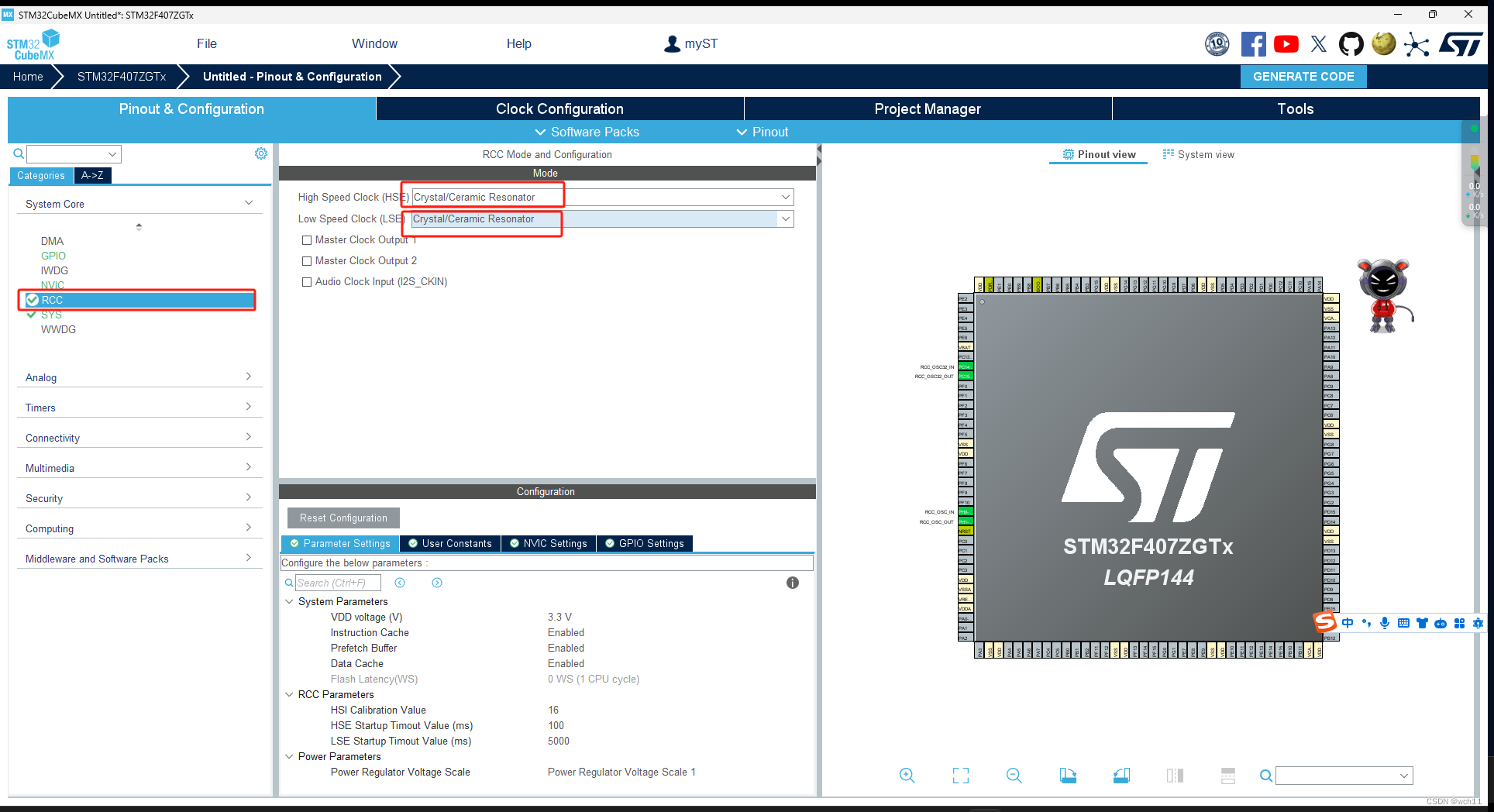
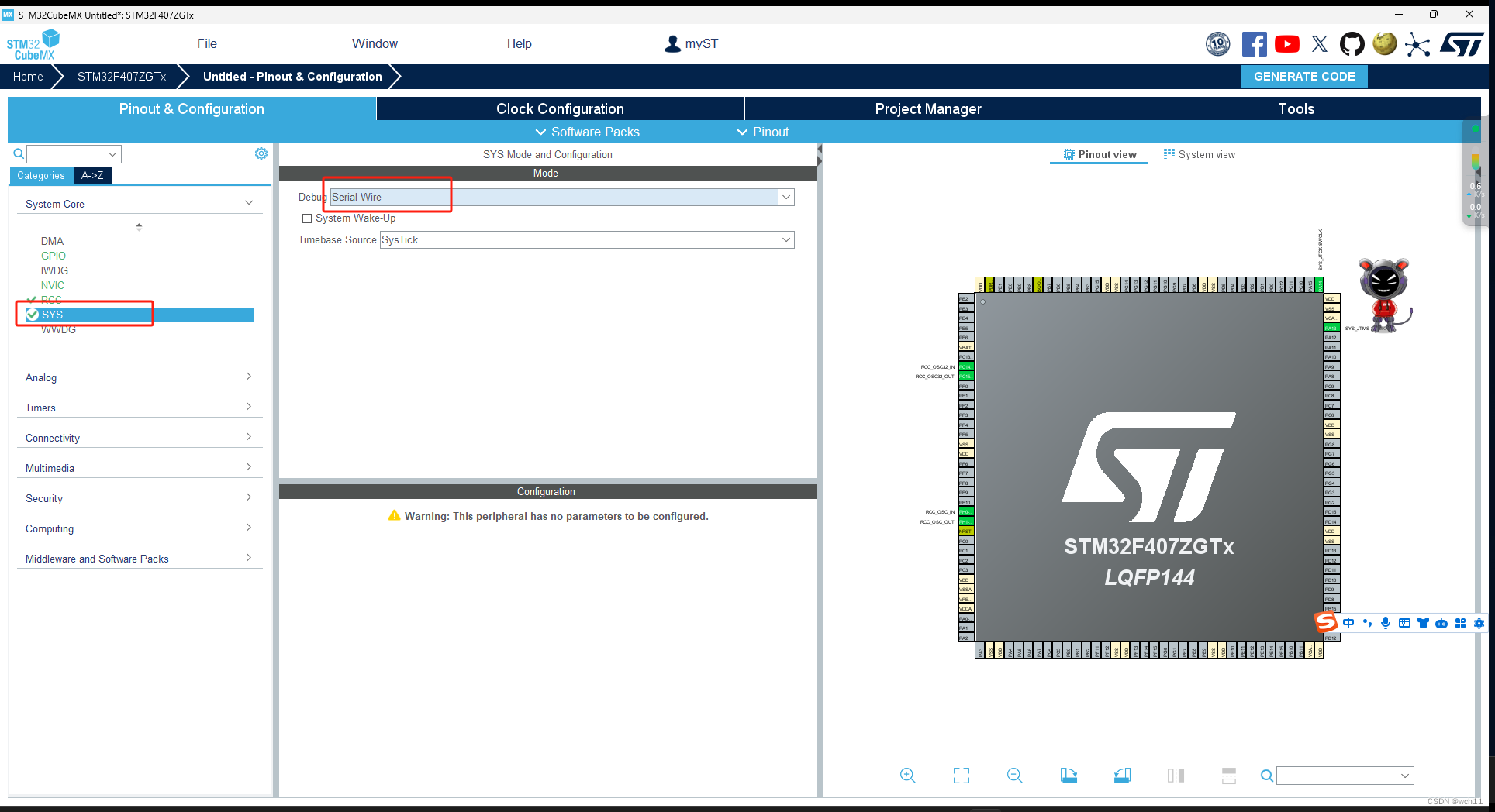
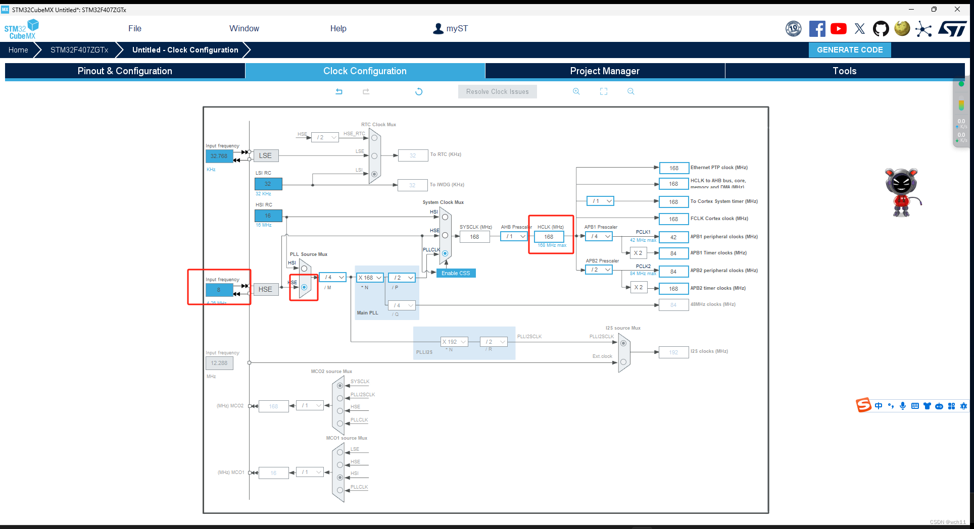
三、cubemx配置
3.1 初始化配置
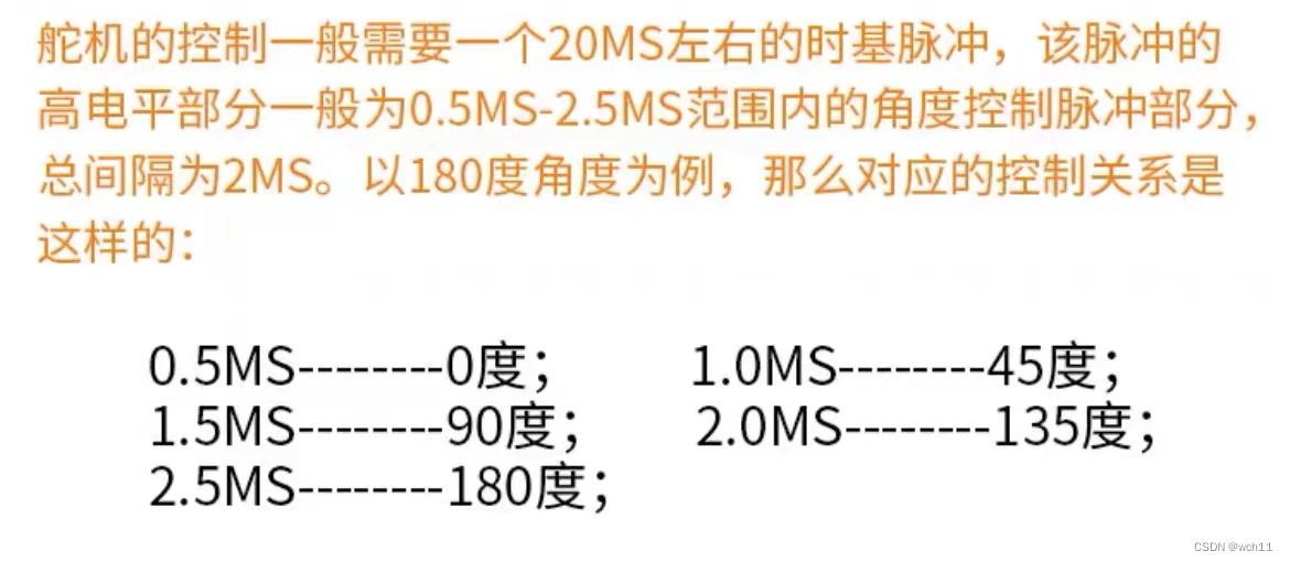
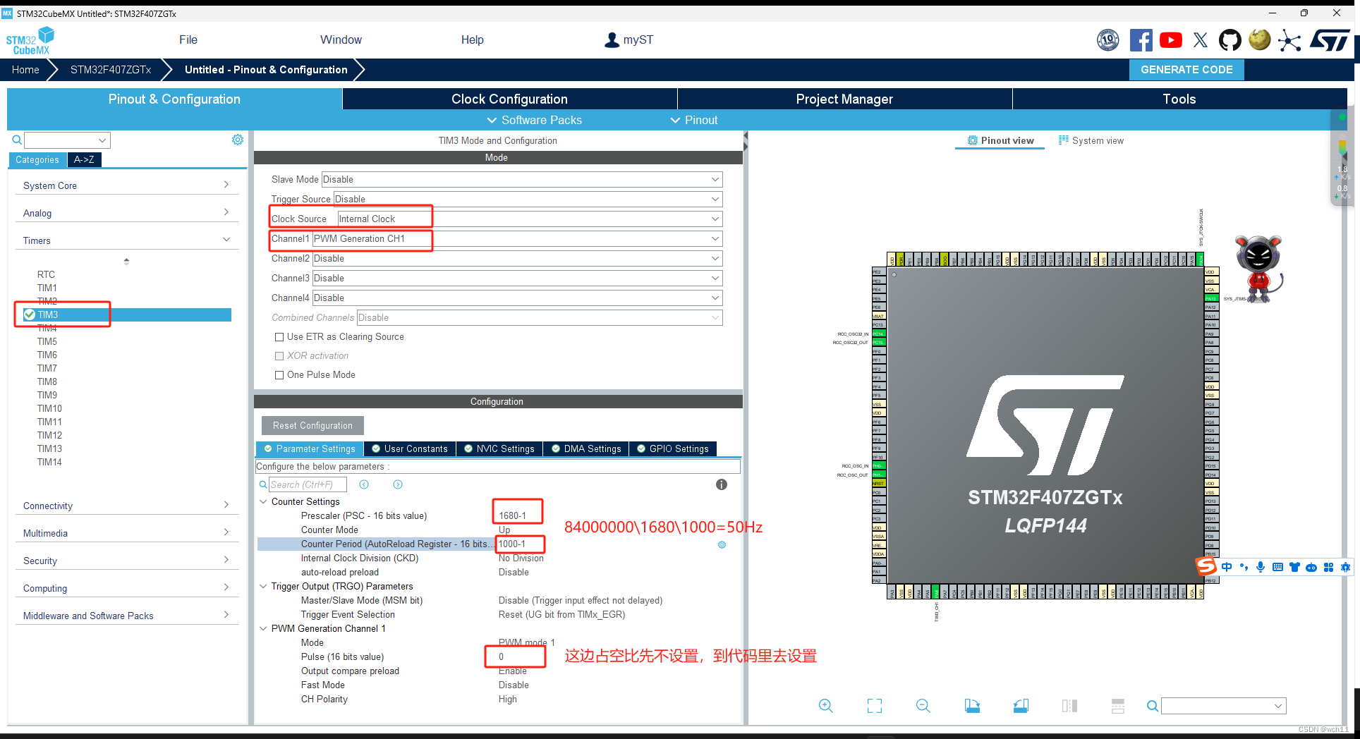
3.2 定时器配置(pwm波输出)
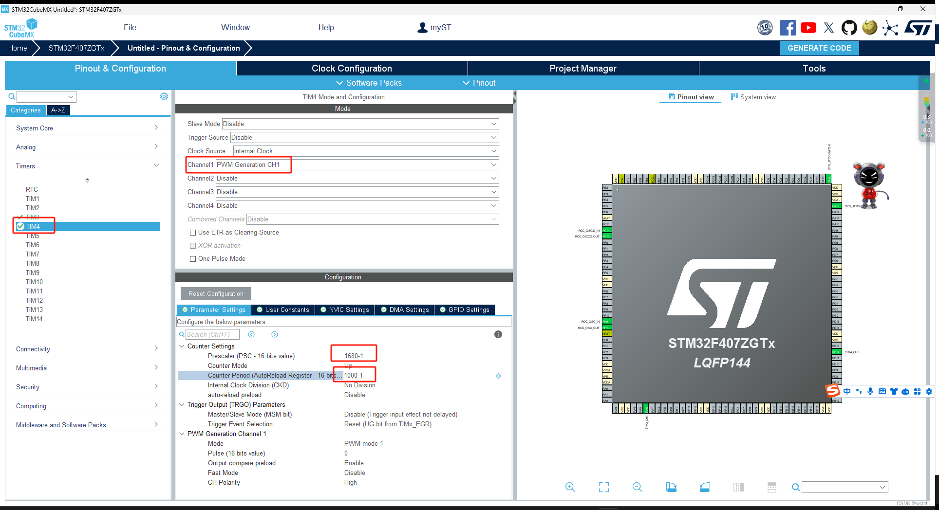
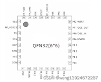
这里我使用tim3的通道1和tim4的通道1分别实现对两个舵机的控制,由于我购买的舵机所需要的频率为50hz(如下图)所以下面的pwm频率均是按照50hz配置的。
tim4的配置同理。
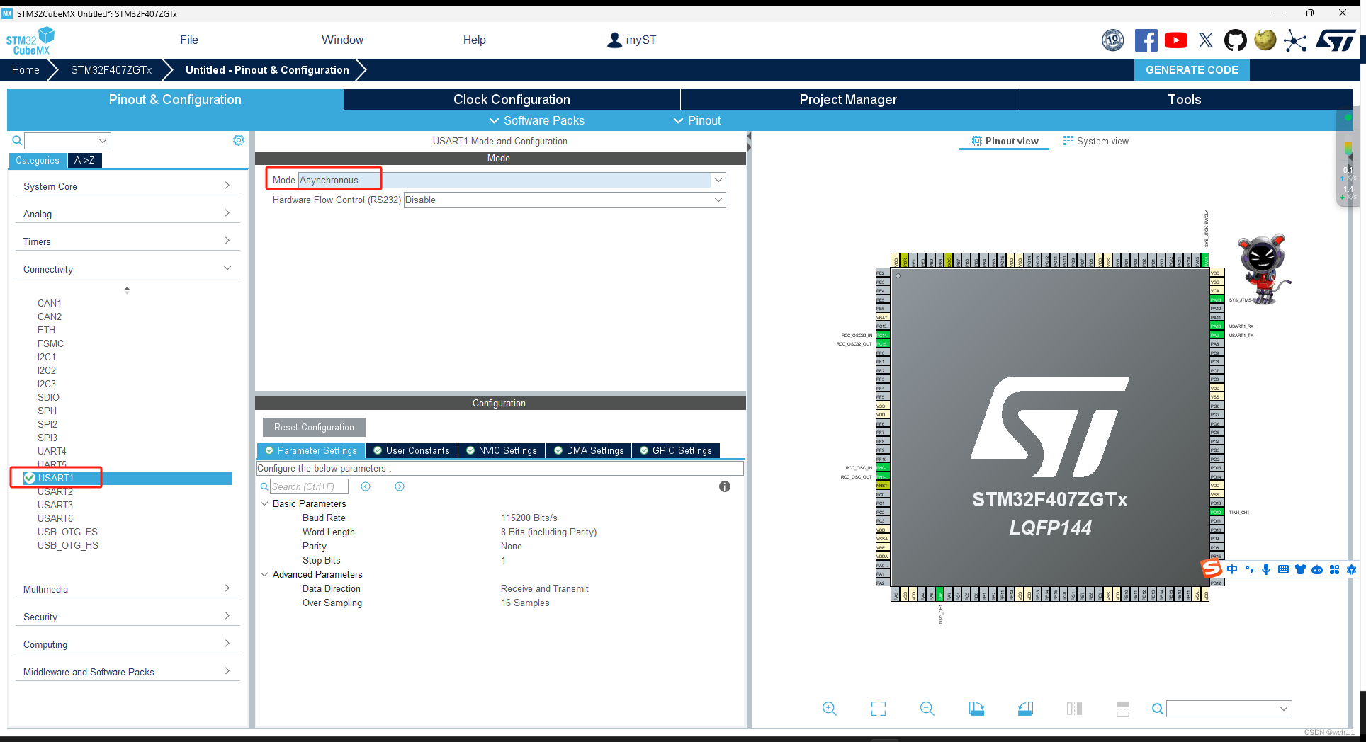
3.3 串口通信配置(与openmv和电脑通信)
为了方便后续的调试,所以建议同时开启与openmv和电脑的通信,即打开两个串口。usart1是用来和电脑通信的,usart2是用来与openmv通信的。
usart2的配置同理。

四、openmv配置
这是openmv中寻找色块,并通过串口pa4,pa5发送中心点位置以及长度和宽度的代码,可以直接复制到openmv ide中。需要注意的是,在openmv中uart_rx—p5 ------ uart_tx—p4。
import time
import sensor
import math
import image
import ustruct
from pyb import uart


uart = uart(3, 115200, timeout_char=200)
uart.init(115200, bits=8, parity=none, stop=1)  # init with given parameters

threshold_index = 0                             # 0 for red, 1 for green, 2 for blue
thresholds = [
    (30, 100, 15, 127, 15, 127),  # generic_red_thresholds
    (30, 100, -64, -8, -32, 32),  # generic_green_thresholds
    (0, 30, 0, 64, -128, 0),      # generic_blue_thresholds
    (82, 100, 75, -49, -22, 31),  # generic_white_thresholds
    (21, 83, 32, 65, 31, 63),
]

sensor.reset()
sensor.set_pixformat(sensor.rgb565)
sensor.set_framesize(sensor.qvga)# qvga的中心坐标:160,120
sensor.skip_frames(time=2000)    # 跳过2000毫秒的帧让相机图像在改变相机设置后稳定下来
sensor.set_auto_gain(false)      # 必须关闭才能进行颜色跟踪
sensor.set_auto_whitebal(false)  # 必须关闭才能进行颜色跟踪
clock = time.clock()

def find_max(blobs):
    max_size=0
    for blob in blobs:
        if blob.pixels() > max_size:
            max_blob = blob
            max_size = blob.pixels()
    return max_blob


def send_data(x,y,w,h):
    global uart;
    fh = bytearray([0xb3,0xb3])     # 帧头
    uart.write(fh)                  # 写到串口

    uart.write(str(x))
    uart.write(bytearray([0x20]))   # 发送空格
    uart.write(str(y))
    uart.write(bytearray([0x20]))
    uart.write(str(w))
    uart.write(bytearray([0x20]))
    uart.write(str(h))

    uart.write(bytearray([0x20]))
    fh = bytearray([0x0d,0x0a])     # 帧尾,换行和回车的ascll
    uart.write(fh)


while true:
    clock.tick()
    img = sensor.snapshot()
    blobs = img.find_blobs([thresholds[threshold_index]])

    #如果找到了目标颜色
    if blobs:
        max_blob = find_max(blobs)
        cx=max_blob[5]
        cy=max_blob[6]
        cw=max_blob[2]
        ch=max_blob[3]

        # 这些值取决于max_blob不是圆形的,否则它们将不稳定.
        # 检查max_blob是否显著偏离圆形
        if max_blob.elongation() > 0.5:
            img.draw_edges(max_blob.min_corners(), color=(255, 0, 0))
            img.draw_line(max_blob.major_axis_line(), color=(0, 255, 0))
            img.draw_line(max_blob.minor_axis_line(), color=(0, 0, 255))

        # 这些值始终是稳定的。
        # img.draw_rectangle(max_blob.rect())
        img.draw_rectangle(160,120,35,35)
        img.draw_cross(cx, cy)

        # 注意-max_blob旋转仅限于0-180。
        img.draw_keypoints(
            [(cx, cy, int(math.degrees(max_blob.rotation())))], size=20
        )

        send_data(cx,cy,cw,ch)      # 发送数据

        print(cx,cy,cw,ch)
        print(clock.fps())
五、keil代码修改
5.1 串口重定义
在usart.c的最后加入重定义代码。
/* user code begin 1 */
int fputc(int ch, file *f)
{
  hal_uart_transmit(&huart1, (uint8_t *)&ch, 1, 0xffff);
  return ch;
}
int fgetc(file *f)
{
  uint8_t ch = 0;
  hal_uart_receive(&huart1, &ch, 1, 0xffff);
  return ch;
}

/* user code end 1 */
在usart.h的开头加入include。
/* user code begin includes */
#include <stdio.h>
/* user code end includes */
5.2 串口回调函数
用到的变量初始化,大家自行放到main.c中的相应位置。
#include "string.h"
#include "stdio.h"
#include "stdlib.h"

#define rxbuffersize  256

char rxbuffer[rxbuffersize],rx_buf[rxbuffersize];
uint8_t arxbuffer;
uint8_t uart1_rx_cnt = 0;
int flag=0;

printf("hello world!\r\n");
hal_delay(200);
hal_uart_receive_it(&huart2, (uint8_t *)&arxbuffer, 1);
这段代码放在main.c中,这里为了方便确定openmv与stm32之间有数据传输,加入了翻转led灯,大家可以有需要可以自己再配置一下led,不用的话可自行删除。
/* user code begin 4 */
void hal_uart_rxcpltcallback(uart_handletypedef *huart)
{
    unused(huart);
	if(huart==&huart2){
		hal_gpio_togglepin(gpiof,led_pin);		//有数据则翻转led灯

		rxbuffer[uart1_rx_cnt] = arxbuffer;
		uart1_rx_cnt++;
		if((rxbuffer[uart1_rx_cnt-1] == 0xb3)&&(rxbuffer[uart1_rx_cnt-2] == 0xb3)) flag=1;		 //帧头判定
		else if((rxbuffer[uart1_rx_cnt-2] == 0x0d)&&(rxbuffer[uart1_rx_cnt-1] == 0x0a)) flag=2;  //帧尾判定
		else flag=0;

		switch (flag)
        {
        	case 1:
				uart1_rx_cnt = 0;
				memset(rxbuffer,0x00,sizeof(rxbuffer));
        		break;
        	case 2:
				rxbuffer[uart1_rx_cnt-1] = '\0';
				rxbuffer[uart1_rx_cnt-2] = '\0';
				strcpy(rx_buf,rxbuffer);
				printf("%s\r\n",rx_buf);
				while(hal_uart_getstate(&huart2) == hal_uart_state_busy_tx);
				uart1_rx_cnt = 0;
				memset(rxbuffer,0x00,sizeof(rxbuffer));
        		break;
			default:break;
        }
	hal_uart_receive_it(&huart2, (uint8_t *)&arxbuffer, 1);
	}
}
/* user code end 4 */
5.3 加入pid控制文件
5.3.1 pid.c
由于两个舵机分别控制横向和纵向的移动,所以此处定义了两个句柄和两个pid函数,分别对应两个舵机,大家可以自行调试其中kp,ki,kd的值。
#include "pid.h"

pid_typedef pid1;
pid_typedef pid2;

void pid_init(void)

{

    pid1.setposition=0;
    pid1.actualposition=0.0;
    pid1.err=0.0;
    pid1.err_last=0.0;
    pid1.out=0.0;
    pid1.integral=0.0;
    pid1.kp=0.025;
    pid1.ki=0;
    pid1.kd=0.017;

	pid2.setposition=0;
    pid2.actualposition=0.0;
    pid2.err=0.0;
    pid2.err_last=0.0;
    pid2.out=0.0;
    pid2.integral=0.0;
    pid2.kp=0.025;
    pid2.ki=0;
    pid2.kd=0.017;
}


float pidx_realize(float actualposition,float setposition)
{
	pid1.actualposition=actualposition;
	pid1.setposition=setposition;
    pid1.err=pid1.setposition-pid1.actualposition;
    pid1.integral+=pid1.err;
    pid1.out=pid1.kp*pid1.err+pid1.ki*pid1.integral+pid1.kd*(pid1.err-pid1.err_last);
    pid1.err_last=pid1.err;

    return pid1.out;
}

float pidy_realize(float actualposition,float setposition)
{
	pid2.actualposition=actualposition;
	pid2.setposition=setposition;
    pid2.err=pid2.actualposition-pid2.setposition;
    pid2.integral+=pid2.err;
    pid2.out=pid2.kp*pid2.err+pid2.ki*pid2.integral+pid2.kd*(pid2.err-pid2.err_last);
    pid2.err_last=pid2.err;

    return pid2.out;
}
5.3.2 pid.h
#ifndef __pid_h
#define __pid_h
#include "stm32f4xx.h"

typedef struct
{
	float setposition;//设定值
	float actualposition;//实际值
	float err;
	float err_last;
	float kp;
	float ki;
	float kd;
	float out;//执行器的变量
	float integral;//积分值
}pid_typedef;

void pid_init(void);
float pidx_realize(float actualposition,float setposition);
float pidy_realize(float actualposition,float setposition);

#endif
添加好文件之后不要忘记添加pid.h的目录 。
5.4 实现对pwm波占空比的控制
放置在前面的初始化代码。
#include "pid.h"

double motor1=25;
double motor2=35;
int cx,cy;

pid_init();
hal_delay(100) ;
hal_tim_pwm_start(&htim3, tim_channel_1);//开启pwm波
hal_tim_pwm_start(&htim4, tim_channel_1);
__hal_tim_set_compare(&htim3, tim_channel_1, motor1);//占空比初始化,为25\1000=2.5%
__hal_tim_set_compare(&htim4, tim_channel_1, motor2);
放在中断回调函数中的代码,可以选择放在case2中的printf下面,因为在openmv中设定的qvga的中心坐标为160,120,所以下列的设定横纵坐标分别为160和120。其中舵机2我设定的占空比在3.5%和6%之间是因为我的装置结构问题,如果上面的电机往下太多会导致数据线与底座接触,造成电机卡住,大家可以根据自己的装配情况自行更改占空比的上下范围。
sscanf(rx_buf, "%d %d", &cx, &cy);//提取rx_buf中的前两个数字,即为横纵坐标
//对下面对应横坐标的舵机进行控制
motor1=motor1+pidx_realize(cx,160);//第一参数为实际坐标,第二个参数为设定坐标
if(motor1<25)motor1=25;//防止超过舵机的工作范围内的占空比
if(motor1>125)motor1=125;
tim3->ccr1=motor1;
//对上面对应纵坐标的舵机进行控制
motor2=motor2+pidy_realize(cy,120);
if(motor2<35)motor2=35;
if(motor2>60)motor2=60;
tim4->ccr1=motor2;
六、成果展示
由于实验室器材有限,无奈拿了一个开学典礼的灯作为底座,所以在舵机运行起来时会不稳,建议大家把舵机固定在重一点且高一点的东西上,可以避免openmv的线被卡住。总体来说,摄像头的跟踪效果还是不错的。
色块跟踪
七、结语
大家如果想要购买我的同款舵机,可以私信我,但是这个舵机的装配比较麻烦,需要自己用工具把材料修剪到合适的大小。然后这是我写的第一份博客,内容可能有不足的地方,大家都可以指出,最后为大家分享几篇我在做的过程中参考的文章,其中第一篇来自我同实验室的同学。

发表评论