文章目录
msp432p401r基础使用
一、gpio输出 点灯 跑马灯
(一)gpio输出
打开芯片数据手册(msp432p401r)第17页的表详细描述了对应引脚的gpio功能
1.库函数
- 配置gpio模式:
gpio_setaoutputpin(port,pin)//设置gpio为输出模式
- 设置高低电平
gpio_setoutputhoghonpin(port,pin)//设置gpio为高电平
gpio_setoutputlowonpin(port,pin)//设置gpio为低电平
gpio_toggleoutputonpin(port,pin)//翻转gpio引脚电平
- 配置驱动强度
只有p2.0、p2.1、p2.2、p2.3引脚可以配置为高驱动程度
this i/o can be configured for high drive operation with up to 20-ma drive capability.
此i/o可配置为高达20 ma驱动能力的高驱动操作。
gpio_setdrivestrengthhigh(port,pin)//强驱动
gpio_setdrivestrengthlow(port,pin)//弱驱动(无特殊要求,一般不用设置)
//几乎不用,需要使用时自行查看参数、返回值等详细信息
#include <ti/devices/msp432p4xx/driverlib/driverlib.h>

int main(void)
{
    // 初始化 msp432p401r 微控制器
    map_wdt_a_holdtimer();

    // 配置 p1.0 引脚为输出模式
    map_gpio_setasoutputpin(gpio_port_p1, gpio_pin0);

    // 设置 p1.0 引脚的驱动强度为高级别
    map_gpio_setdrivestrengthhigh(gpio_port_p1, gpio_pin0);

    while (1)
    {
        // 在 p1.0 引脚输出高电平
        map_gpio_setoutputhighonpin(gpio_port_p1, gpio_pin0);

        // 延时约一秒钟
        map_pcm_gotolpm0();
    }
}
(二)点亮led灯
1.硬件连接
可以打开评估版手册(msp432开发板手册/slau597f)37页原理图
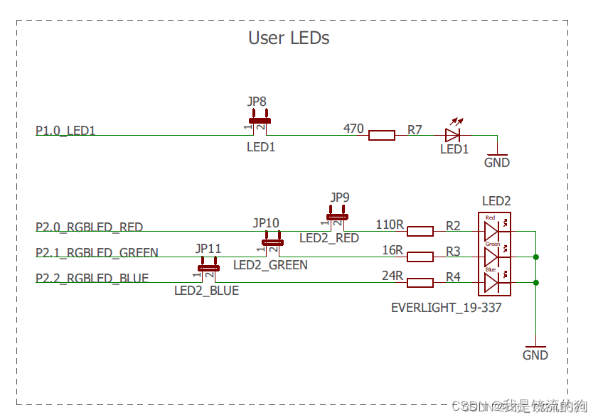
共阴极连接,高电平亮,低电平熄灭
2.代码
led.h
#ifndef __led_h
#define __led_h
#include <ti/devices/msp432p4xx/driverlib/driverlib.h>

// 位带操作
#define led_red bitband_peri(p1out,0)
#define led_r bitband_peri(p2out,0)
#define led_g bitband_peri(p2out,1)
#define led_b bitband_peri(p2out,2)

void led_init(void);//led初始化函数

void led_red_on(void);//打开led1
void led_red_off(void);//关闭led1
void led_red_tog(void);//翻转led1

void led_y_on(void);//打开黄色rgb灯
void led_c_on(void);//打开青色rgb灯
void led_p_on(void);//打开品红rgb灯

void led_r_on(void);//红色rgb灯
void led_g_on(void);//绿色rgb灯
void led_b_on(void);//蓝色rgb灯

void led_r_off(void);
void led_g_off(void);
void led_b_off(void);

void led_r_tog(void);
void led_g_tog(void);
void led_b_tog(void);

void led_w_on(void);//白色rgb灯
void led_w_off(void);
void led_w_tog(void);

#endif
led.c
#include "led.h"

void led_init(void)
{
    map_gpio_setasoutputpin(gpio_port_p1, gpio_pin0);//设置gpio为输出模式
    map_gpio_setasoutputpin(gpio_port_p2, gpio_pin0 + gpio_pin1 + gpio_pin2);

    led_red_off();
    led_r_off();
    led_g_off();
    led_b_off();
}
void led_red_on(void) { led_red = 1; }
void led_red_off(void) { led_red = 0; }
void led_red_tog(void) { led_red ^= 1; }

void led_r_off(void) { led_r = 0;}
void led_g_off(void) { led_g = 0;}
void led_b_off(void) { led_b = 0; }

void led_r_on(void) { led_r = 1; }
void led_g_on(void) { led_g = 1;  }
void led_b_on(void) { led_b = 1;  }

void led_r_tog(void) { led_r ^= 1; }
void led_g_tog(void) { led_g ^= 1; }
void led_b_tog(void) { led_b ^= 1; }

//白色 white
void led_w_on(void)
{
    led_r_on();
    led_g_on();
    led_b_on();
}
//白色 white
void led_w_off(void)
{
    led_r_off();
    led_g_off();
    led_b_off();
}
//白色 white
void led_w_tog(void)
{
    led_r_tog();
    led_g_tog();
    led_b_tog();
}
//黄色 yellow
void led_y_on(void)
{
    led_r_on();
    led_g_on();
    led_b_off();
}
//品红 pinkish red
void led_p_on(void)
{
    led_r_on();
    led_g_off();
    led_b_on();
}
//青色 cyan
void led_c_on(void)
{
    led_r_off();
    led_g_on();
    led_b_on();
}
main.c
#include <ti/devices/msp432p4xx/driverlib/driverlib.h>

/* standard includes */
#include <stdint.h>
#include <stdbool.h>

#include "led.h"

int main(void)
{
    uint32_t i;

    /* stop watchdog  */
    map_wdt_a_holdtimer();//关闭看门狗

    led_init();//led初始化

    while (1)
    {
        led_red_on();
        for (i = 0; i < 500000; i++);
        led_red_off();

        led_r_on();
        for (i = 0; i < 500000; i++);
        led_r_off();

        led_g_on();
        for (i = 0; i < 500000; i++);
        led_g_off();

        led_b_on();
        for (i = 0; i < 500000; i++);
        led_b_off();

		led_c_on();
        for (i = 0; i < 500000; i++);

		led_p_on();
        for (i = 0; i < 500000; i++);

		led_y_on();
        for (i = 0; i < 500000; i++);

		led_w_on();
        for (i = 0; i < 500000; i++);
        led_w_off();
    }
}
二、gpio做输入 按键输入
(一)gpio做输入
1.库函数
配置gpio模式:
gpio_setaslnputpin(port,pin);//设置为浮空输入
gpio_setaslnputwithpullupresistor(port,pin);//设置为上拉输入模式
gpio_setaslnputwithpulldownresistor(port,pin);//设置为下拉输入模式
获取电平状态:
gpio_getlnputpinvalue(port,pin);
(二)按键输入
1.硬件连接
可以打开评估版手册(msp432开发板手册/slau597f)37页原理图
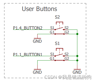
可以看到按下后被拉低为低电平,所以我们应该把引脚配置为上拉输入
2.代码
key.h
#ifndef __key_h
#define __key_h

#include "driverlib.h"

#define key1 bitband_peri(p1in, 1) //读取按键1
#define key2 bitband_peri(p1in, 4) //读取按键2


#define key1_pres 	1	//key0按下
#define key2_pres	  2	//key1按下


void key_init(void);//io初始化
uint8_t key_scan(uint8_t);  	//按键扫描函数
#endif
key.c
#include "driverlib.h"
#include "key.h"

//按键初始化函数
void key_init(void) //io初始化
{
	gpio_setasinputpinwithpullupresistor(gpio_port_p1, gpio_pin1 | gpio_pin4);
}

//按键处理函数
//返回按键值
//mode:0,不支持连续按;1,支持连续按;
//0,没有任何按键按下
//1,key0按下
//2,key1按下
//3,key3按下 wk_up
//注意此函数有响应优先级,key0>key1>key_up!!
uint8_t key_scan(uint8_t mode)
{
	uint16_t i;
	static uint8_t key_up = 1; //按键按松开标志
	if (mode)
		key_up = 1; //支持连按
	if (key_up && (key2 == 0 || key1 == 0))
	{
		for (i = 0; i < 5000; i++)
			; //去抖动
		key_up = 0;
		if (key1 == 0)
			return key1_pres;
		else if (key2 == 0)
			return key2_pres;
	}
	else if (key2 == 1 && key1 == 1)
		key_up = 1;
	return 0;// 无按键按下
}
main.c
#include "driverlib.h"

/* standard includes */
#include <stdint.h>
#include <stdbool.h>

#include "led.h"
#include "key.h"

int main(void)
{

		uint8_t key;

    /* stop watchdog  */
    map_wdt_a_holdtimer();

    led_init();
    key_init();

    while (1)
    {
				key = key_scan(0);//不支持连按

				if (key == key1_pres)
						led_red_on();//打开led1
				else if (key == key2_pres)
						led_red_off();//关闭led1

    }
}
三、外部中断
msp432p401r并不是每一个io口都可以中断,必须参考msp432p401r第17页
![[外链图片转存失败,源站可能有防盗链机制,建议将图片保存下来直接上传(img-jwuq1klo-1690345264992)(d:\typora\图片\image-20230721141203189.png)]](https://images.3wcode.com/3wcode/20240801/b_0_202408010027162493.jpg)
port interrupt:端口中断
只有p1到p7所以io口可以做外部中断
(一)库函数
1.gpio.h
- (1)开启外部中断
gpio_enableinterrupt(gpio_port_px,gpio_pinx);
- 配置触发方式
gpio_interruptedgeselect(gpio_port_p1,gpio_pin4,edge);
edge有效值:
gpio_high_to_low_transition//下降沿(从高到低)
gpio_low_to_high_transition//上升沿(从低到高)
- 获取gpio中断状态
gpio_getenabledinterruptstatus(gpio_port_px);
- 清除gpio中断标志位
gpio_clearinterruptflag(gpio_port_px,gpio_pinx);
配合使用
status=gpio_getenabledinterruptstatus(gpio_port_px);
gpio_clearinterruptflag(gpio_port_px,status);
2.interrupt.h
- 开启总中断
interrupt_enablemaster(void);
- 开启端口中断
interrupt_enableinterrupt(interruptnumber);
interruptnumber有效值:
int_port1
int_port2
int_port3
int_port4
int_port5
int_port6
(二)一般配置步骤
-
配置gpio输入
gpio_setasinputpinwithpullupresistor(gpio_port_p1, gpio_pin1); //p1.1 gpio_setasinputpinwithpullupresistor(gpio_port_p1, gpio_pin4); //p1.4 -
清除中断标志位
gpio_clearinterruptflag(gpio_port_p1, gpio_pin1); gpio_clearinterruptflag(gpio_port_p1, gpio_pin4); -
配置触发方式
gpio_interruptedgeselect(gpio_port_p1, gpio_pin1, gpio_high_to_low_transition); gpio_interruptedgeselect(gpio_port_p1, gpio_pin4, gpio_high_to_low_transition); -
开启外部中断
gpio_enableinterrupt(gpio_port_p1, gpio_pin1); gpio_enableinterrupt(gpio_port_p1, gpio_pin4); -
开启端口中断
interrupt_enableinterrupt(int_port1); -
开启总中断
interrupt_enablemaster(); -
编写中断服务函数
void port1_irqhandler(void)
{
	uint16_t status;

	status = gpio_getenabledinterruptstatus(gpio_port_p1);
	gpio_clearinterruptflag(gpio_port_p1, status);
	delay_ms(10);//按键消抖

	if (status & gpio_pin1) //对应p1.1
	{
		if (key1 == 0)
		{
			led_red_on(); //点亮红灯

		}
	}
	if (status & gpio_pin4) //对应p1.4
	{
		if (key2 == 0)
		{
			led_red_tog();//翻转红灯

		}
	}
}
(三)中断优先级管理
详情见技术手册(slau356)82页
-
等级越低,中断优先级越高,也就是说等级0的优先级最高。
-
支持动态调整优先级
-
将优先级分为组优先级和子优先级,组优先级高的是可以打断组优先级低的,组优先级一样时就不会被打断,如果发生了两个组优先级一样的中断,则子优先级高的会先执行,另一个挂起
-
注意,这里的子优先级是硬件优先级,是已经设置好了的,不能更改
详情见msp432p401r第117页,中断号(nvic interrupt input)越小,子优先级越高
例子:
系统有两个中断,中断a和中断b,中断号分别为1和2。
当不进行中断优先级配置时,组优先级一致,中断号即为中断优先级,中断号小的中断优先级高,所以中断优先级为a>b。假如此时系统正在执行中断b,而中断a发生了,系统会如何处理呢?因为它们组优先级一样,故中断a不能打断中断b,系统会先挂起中断a,待中断b执行完后,再执行中断a;
倘若将中断a的组优先级设置为1,中断b的组优先级设置为2,此时系统正在执行中断b,而中断a发生了,系统会如何处理呢?因为组优先级小的优先级高,所以中断优先级是a>b,故系统打断中断b,执行中断a,待中断a执行完后,再继续执行中断b。
总结:
- 组优先级高的能打断组优先级低的
- 在组优先级一样的情况下,子优先级高的不能打断子优先级低的
1.代码
- 设置组优先级
interrupt_setpriority(interruptnuber,level);
level:x<<5,x∈[0,7]
只使用高3位,配置时左移5位。
(四)外部中断实验
exti.h
#ifndef __exti_h
#define __exit_h
#include "driverlib.h"

void extix_init(void);//外部中断初始化


#endif
exti.c
#include "driverlib.h"
#include "exti.h"


void extix_init(void)
{
	//1.配置gpio输入
	gpio_setasinputpinwithpullupresistor(gpio_port_p1, gpio_pin1); //p1.1
	gpio_setasinputpinwithpullupresistor(gpio_port_p1, gpio_pin4); //p1.4

	//2.清除中断标志位
	gpio_clearinterruptflag(gpio_port_p1, gpio_pin1);
	gpio_clearinterruptflag(gpio_port_p1, gpio_pin4);

	//3.配置触发方式
	gpio_interruptedgeselect(gpio_port_p1, gpio_pin1, gpio_high_to_low_transition);
	gpio_interruptedgeselect(gpio_port_p1, gpio_pin4, gpio_high_to_low_transition);

	//4.5 配置组优先级
	interrupt_setpriority(int_port1, 1 << 5);
	interrupt_setpriority(int_port1, 2 << 5);

	//4.开启外部中断
	gpio_enableinterrupt(gpio_port_p1, gpio_pin1);
	gpio_enableinterrupt(gpio_port_p1, gpio_pin4);

	//5.开启端口中断
	interrupt_enableinterrupt(int_port1);

	//6.开启总中断
	interrupt_enablemaster();
}
main.h
#include "driverlib.h"

/* standard includes */
#include <stdint.h>
#include <stdbool.h>

#include "led.h"
#include "key.h"
#include "delay.h"
#include "exti.h"

int main(void)
{

    /* stop watchdog  */
    map_wdt_a_holdtimer();

    led_init();
    extix_init();
		delay_init();
    while (1)
    {
    }
}

//7.编写中断服务函数
void port1_irqhandler(void)
{
	uint16_t status;

	status = gpio_getenabledinterruptstatus(gpio_port_p1);
	gpio_clearinterruptflag(gpio_port_p1, status);
	delay_ms(10);//按键消抖

	if (status & gpio_pin1) //对应p1.1
	{
		if (key1 == 0)
		{
			led_red_on(); //点亮红灯

		}
	}
	if (status & gpio_pin4) //对应p1.4
	{
		if (key2 == 0)
		{
			led_red_tog();//翻转红灯

		}
	}
}
四、串口收发
(一)msp432p401r串口资源+
![[外链图片转存失败,源站可能有防盗链机制,建议将图片保存下来直接上传(img-wwrtfid0-1690345264992)(d:\typora\图片\image-20230704220945418.png)]](https://images.3wcode.com/3wcode/20240801/b_0_202408010027178107.jpg)
详见msp432p401r第6页
a0的串口是通过跳线帽连接到调试器上的
![[外链图片转存失败,源站可能有防盗链机制,建议将图片保存下来直接上传(img-wuvcytel-1690345264992)(d:\typora\图片\image-20230704221144484.png)]](https://images.3wcode.com/3wcode/20240801/b_0_202408010027175035.jpg)
开发板手册(slau597f)第38页
(二)uart模式的特性
- 7/8个数据位、1个奇/偶/无奇偶效验位
- 独立的发送和接收移位寄存器
- 独立的发送和接收缓冲寄存器
- lsp优先/msb优先的数据发送和接收
- 为多处理器系统内置空闲线和地址位通信协议
- 支持分数波特率的可编程调制波特率
- 用于错误检测和抑制的状态标志
- 针对地址检测的状态标志
- 针对接收、发送,起始位接收和发送完成的独立中断能力
数据手册(slau356)第904页
(三)库函数
1.uart.h
-
初始化串口函数
uart_initmodule(eusci_ax_base, &uartconfig); -
使能串口模块
uart_enablemodule(eusci_ax_base); -
开启串口相关中断
uart_enableinterrupt(eusci_ax_base, eusci_x_interrupt); -
获取数据
uart_receivedata(eusci_ax_base); -
发送数据
uart_transmitdata(eusci_ax_base,data_8bit); -
开启串口端口中断
interrupt_enableinterrupt(int_eusciax); -
开启总中断
interrupt_enablemaster(void);
(四)一般配置步骤
- 配置时钟
- 配置gpio复用
- 配置结构体
- 初始化串口
- 开启串口
- 开启串口相关中断
- 开启串口端口中断
- 开启总中断
- 编写uart isr
(五)代码
usart.h
/****************************************************/
// msp432p401r
// 串口配置
// bilibili:m-rna
// e-mail:m-rna@qq.com
/****************************************************/

/******************   版本更新说明   *****************
 *
 * ccs支持printf
 * keil支持标准c库跟微库
 * 用keil开发终于可以不开微库啦
 *
 * ? 需要注意:
 * ①使用标准c库时,将无法使用scanf。
 * 如果需要使用scanf时,请使用微库 microlib
 * ①低频时钟频率下,高波特率使得传输时误差过大,
 * 比如35768hz下19200波特率,
 * 会使得传输出错,这时可以尝试降低波特率。
 * ②baudrate_calculate的问题请去文件内查看。
 *
 * **************************************************
 *
 * ? v3.2  2021/10/28
 * 简化对ccs支持的printf代码
 *
 * ? v3.1  2021/10/18
 * 添加对ccs的printf支持
 *
 * ? v3.0  2021/10/15
 * 此版本支持使用 标准c库
 * 文件正式改名为与正点原子同名的
 * usart.c 和 usart.h,方便移植
 * 仅支持keil平台开发
 *
 * ? v2.1  2021/8/27
 * 添加支持固件库v3_21_00_05
 * 仅支持 microlib 微库、keil平台开发
 *
 * ? v2.0  2021/8/25
 * uart_init增添了波特率传入参数,可直接配置波特率。
 * 计算uart的代码单独打包为名为
 * baudrate_calculate的c文件和h文件
 * 仅支持 microlib 微库、keil平台开发
 *
 * ? v1.0 2021/7/17
 * 仅支持固件库v3_40_01_02
 * 配置了smclk 48mhz 波特率 115200的初始化代码,
 * 对接标准输入输出库,使其能使用printf、scanf函数
 * 仅支持 microlib 微库、keil平台开发
 *
 ****************************************************/

#ifndef __usart_h
#define __usart_h
#include "driverlib.h"
#include "stdio.h" //1.61328125kb

#ifdef __ti_compiler_version__
//ccs平台
#include "stdarg.h"
#include "string.h"
#define usart0_max_send_len     600                 //最大发送缓存字节数
int printf(const char *str, ...);
#endif

void uart_init(uint32_t baudrate);

#endif
usart.c
/****************************************************/
// msp432p401r
// 串口配置
// bilibili:m-rna
// e-mail:m-rna@qq.com
/****************************************************/

/******************   版本更新说明   *****************
 *
 * ccs支持printf
 * keil支持标准c库跟微库
 * 用keil开发终于可以不开微库啦
 *
 * ? 需要注意:
 * ①使用标准c库时,将无法使用scanf。
 * 如果需要使用scanf时,请使用微库 microlib
 * ①低频时钟频率下,高波特率使得传输时误差过大,
 * 比如35768hz下19200波特率,
 * 会使得传输出错,这时可以尝试降低波特率。
 * ②baudrate_calculate的问题请去文件内查看。
 *
 * **************************************************
 *
 * ? v3.2  2021/10/28
 * 简化对ccs支持的printf代码
 *
 * ? v3.1  2021/10/18
 * 添加对ccs的printf支持
 *
 * ? v3.0  2021/10/15
 * 此版本支持使用 标准c库
 * 文件正式改名为与正点原子同名的
 * usart.c 和 usart.h,方便移植
 * 仅支持keil平台开发
 *
 * ? v2.1  2021/8/27
 * 添加支持固件库v3_21_00_05
 * 仅支持 microlib 微库、keil平台开发
 *
 * ? v2.0  2021/8/25
 * uart_init增添了波特率传入参数,可直接配置波特率。
 * 计算uart的代码单独打包为名为
 * baudrate_calculate的c文件和h文件
 * 仅支持 microlib 微库、keil平台开发
 *
 * ? v1.0 2021/7/17
 * 仅支持固件库v3_40_01_02
 * 配置了smclk 48mhz 波特率 115200的初始化代码,
 * 对接标准输入输出库,使其能使用printf、scanf函数
 * 仅支持 microlib 微库、keil平台开发
 *
 ****************************************************/

#include "usart.h"
#include "baudrate_calculate.h"

#ifdef __ti_compiler_version__
//ccs平台
uint8_t  usart0_tx_buf[usart0_max_send_len];             //发送缓冲,最大usart3_max_send_len字节
int printf(const char *str, ...)
{
    uint16_t i,j;
    va_list ap;
    va_start(ap,str);
    vsprintf((char*)usart0_tx_buf,str,ap);
    va_end(ap);
    i=strlen((const char*)usart0_tx_buf);       //此次发送数据的长度
    for(j=0;j<i;j++)                            //循环发送数据
    {
      //while(usart_getflagstatus(usart3,usart_flag_tc)==reset); //循环发送,直到发送完毕
        uart_transmitdata(eusci_a0_base, usart0_tx_buf[j]);
    }
    return 0;
}
/*****************   函数说明   *****************
 *
 * 函数:int printf(const char *str, ...);
 * 源码来自@正点原子
 * 稍作改动适配ccs工程,在此也表感谢正点原子。
 *
 *****************   说明结束   *****************/

#else
//keil支持标准c库跟微库
//预编译
//if 1 使用标准c库 如果报错就使用微库
//if 0 使用微库 得去勾选魔术棒里的 use microlib
#if 1
#pragma import(__use_no_semihosting)
//标准库需要的支持函数
struct __file
{
  int handle;
};
file __stdout;
//定义_sys_exit()以避免使用半主机模式
void _sys_exit(int x)
{
  x = x;
}
#else
int fgetc(file *f)
{
  while (eusci_a_uart_receive_interrupt_flag !=
         uart_getinterruptstatus(eusci_a0_base, eusci_a_uart_receive_interrupt_flag))
    ;
  return uart_receivedata(eusci_a0_base);
}
#endif
int fputc(int ch, file *f)
{
  uart_transmitdata(eusci_a0_base, ch & 0xff);
  return ch;
}
/*****************   函数说明   *****************
 *
 * 以上两条对接标准输入输出库的函数:
 * int fputc(int ch, file *f);
 * int fgetc(file *f);
 * 源码为bilibili平台up主 “cloudboystudio” 编写
 * 本人rna,不是作者
 * 在此也表感谢
 *
 *****************   说明结束   *****************/
#endif

void uart_init(uint32_t baudrate)
{
#ifdef eusci_a_uart_7_bit_len
  //固件库v3_40_01_02
  //默认smclk 48mhz 比特率 115200
  const eusci_uart_configv1 uartconfig =
      {
          eusci_a_uart_clocksource_smclk,                // smclk clock source
          26,                                            // brdiv = 26
          0,                                             // ucxbrf = 0
          111,                                           // ucxbrs = 111
          eusci_a_uart_no_parity,                        // no parity
          eusci_a_uart_lsb_first,                        // msb first
          eusci_a_uart_one_stop_bit,                     // one stop bit
          eusci_a_uart_mode,                             // uart mode
          eusci_a_uart_oversampling_baudrate_generation, // oversampling
          eusci_a_uart_8_bit_len                         // 8 bit data length
      };
  eusci_calcbauddividers((eusci_uart_configv1 *)&uartconfig, baudrate); //配置波特率
#else
  //固件库v3_21_00_05
  //默认smclk 48mhz 比特率 115200
  const eusci_uart_config uartconfig =
      {
          eusci_a_uart_clocksource_smclk,                // smclk clock source
          26,                                            // brdiv = 26
          0,                                             // ucxbrf = 0
          111,                                           // ucxbrs = 111
          eusci_a_uart_no_parity,                        // no parity
          eusci_a_uart_lsb_first,                        // msb first
          eusci_a_uart_one_stop_bit,                     // one stop bit
          eusci_a_uart_mode,                             // uart mode
          eusci_a_uart_oversampling_baudrate_generation, // oversampling
      };
  eusci_calcbauddividers((eusci_uart_config *)&uartconfig, baudrate); //配置波特率
#endif

  map_gpio_setasperipheralmodulefunctionoutputpin(gpio_port_p1, gpio_pin2 | gpio_pin3, gpio_primary_module_function);//2.配置gpio复用
  map_uart_initmodule(eusci_a0_base, &uartconfig);//3.初始化串口
  map_uart_enablemodule(eusci_a0_base);//4.开启串口模块
	uart_enableinterrupt(eusci_a0_base, eusci_a_uart_receive_interrupt);//5.开启串口相关中断
	interrupt_enableinterrupt(int_euscia0);//6.开启串口端口中断
	interrupt_enablemaster();//7.开启总中断
}

//8.编写uart isr
void euscia0_irqhandler(void)
{
    uint32_t status = uart_getenabledinterruptstatus(eusci_a0_base);

    if(status & eusci_a_uart_receive_interrupt_flag) //接收中断
    {
        uart_transmitdata(eusci_a0_base, map_uart_receivedata(eusci_a0_base)); //发送数据
    }

}
sysinit.h
/* --copyright--,bsd
 * copyright (c) 2017, texas instruments incorporated
 * all rights reserved.
 *
 * redistribution and use in source and binary forms, with or without
 * modification, are permitted provided that the following conditions
 * are met:
 *
 * *  redistributions of source code must retain the above copyright
 *    notice, this list of conditions and the following disclaimer.
 *
 * *  redistributions in binary form must reproduce the above copyright
 *    notice, this list of conditions and the following disclaimer in the
 *    documentation and/or other materials provided with the distribution.
 *
 * *  neither the name of texas instruments incorporated nor the names of
 *    its contributors may be used to endorse or promote products derived
 *    from this software without specific prior written permission.
 *
 * this software is provided by the copyright holders and contributors "as is"
 * and any express or implied warranties, including, but not limited to,
 * the implied warranties of merchantability and fitness for a particular
 * purpose are disclaimed. in no event shall the copyright owner or
 * contributors be liable for any direct, indirect, incidental, special,
 * exemplary, or consequential damages (including, but not limited to,
 * procurement of substitute goods or services; loss of use, data, or profits;
 * or business interruption) however caused and on any theory of liability,
 * whether in contract, strict liability, or tort (including negligence or
 * otherwise) arising in any way out of the use of this software,
 * even if advised of the possibility of such damage.
 * --/copyright--*/
#ifndef __sysctl_h__
#define __sysctl_h__

#include <stdint.h>
#include "driverlib.h"

/* define to ensure that our current msp432 has the sysctl module. this
    definition is included in the device specific header file */
#ifdef __mcu_has_sysctl__

//*****************************************************************************
//
//! \addtogroup sysctl_api
//! @{
//
//*****************************************************************************

//*****************************************************************************
//
// if building with a c++ compiler, make all of the definitions in this header
// have a c binding.
//
//*****************************************************************************
#ifdef __cplusplus
extern "c"
{
#endif

//*****************************************************************************
//
// control specific variables
//
//*****************************************************************************
#define sysctl_sram_bank7 sysctl_sram_banken_bnk7_en
#define sysctl_sram_bank6 sysctl_sram_banken_bnk6_en
#define sysctl_sram_bank5 sysctl_sram_banken_bnk5_en
#define sysctl_sram_bank4 sysctl_sram_banken_bnk4_en
#define sysctl_sram_bank3 sysctl_sram_banken_bnk3_en
#define sysctl_sram_bank2 sysctl_sram_banken_bnk2_en
#define sysctl_sram_bank1 sysctl_sram_banken_bnk1_en

#define sysctl_hard_reset 1
#define sysctl_soft_reset 0

#define sysctl_periph_dma sysctl_perihalt_ctl_halt_dma
#define sysctl_periph_wdt sysctl_perihalt_ctl_halt_wdt
#define sysctl_periph_adc sysctl_perihalt_ctl_halt_adc
#define sysctl_periph_euscib3 sysctl_perihalt_ctl_halt_eub3
#define sysctl_periph_euscib2 sysctl_perihalt_ctl_halt_eub2
#define sysctl_periph_euscib1 sysctl_perihalt_ctl_halt_eub1
#define sysctl_periph_euscib0 sysctl_perihalt_ctl_halt_eub0
#define sysctl_periph_euscia3 sysctl_perihalt_ctl_halt_eua3
#define sysctl_periph_euscia2 sysctl_perihalt_ctl_halt_eua2
#define sysctl_periph_euscia1 sysctl_perihalt_ctl_halt_eua1
#define sysctl_periph_euscia0 sysctl_perihalt_ctl_halt_eua0
#define sysctl_periph_timer32_0_module sysctl_perihalt_ctl_halt_t32_0
#define sysctl_periph_timer16_3 sysctl_perihalt_ctl_halt_t16_3
#define sysctl_periph_timer16_2 sysctl_perihalt_ctl_halt_t16_2
#define sysctl_periph_timer16_1 sysctl_perihalt_ctl_halt_t16_1
#define sysctl_periph_timer16_0 sysctl_perihalt_ctl_halt_t16_0

#define sysctl_nmipin_src sysctl_nmi_ctlstat_pin_src
#define sysctl_pcm_src sysctl_nmi_ctlstat_pcm_src
#define sysctl_pss_src sysctl_nmi_ctlstat_pss_src
#define sysctl_cs_src sysctl_nmi_ctlstat_cs_src

#define sysctl_reboot_key   0x6900

#define sysctl_1_2v_ref        (uint32_t)&tlv->adc14_ref1p2v_ts30c - (uint32_t)tlv_base
#define sysctl_1_45v_ref       (uint32_t)&tlv->adc14_ref1p45v_ts30c - (uint32_t)tlv_base
#define sysctl_2_5v_ref        (uint32_t)&tlv->adc14_ref2p5v_ts30c - (uint32_t)tlv_base

#define sysctl_85_degrees_c    4
#define sysctl_30_degrees_c    0


#define tlv_start               0x00201004
#define tlv_tag_reserved1      1
#define tlv_tag_reserved2      2
#define tlv_tag_cs             3
#define tlv_tag_flashctl       4
#define tlv_tag_adc14          5
#define tlv_tag_reserved6      6
#define tlv_tag_reserved7      7
#define tlv_tag_ref            8
#define tlv_tag_reserved9      9
#define tlv_tag_reserved10     10
#define tlv_tag_devinfo        11
#define tlv_tag_dierec         12
#define tlv_tag_randnum        13
#define tlv_tag_reserved14     14
#define tlv_tag_bsl            15
#define tlv_tagend             0x0bd0e11d

//*****************************************************************************
//
// structures for tlv definitions
//
//*****************************************************************************
typedef struct
{
    uint32_t    maxprogrampulses;
    uint32_t    maxerasepulses;
} sysctl_flashtlv_info;

typedef struct
{
    uint32_t rdcoir_fcal_rsel04;
    uint32_t rdcoir_fcal_rsel5;
    uint32_t rdcoir_maxpostune_rsel04;
    uint32_t rdcoir_maxnegtune_rsel04;
    uint32_t rdcoir_maxpostune_rsel5;
    uint32_t rdcoir_maxnegtune_rsel5;
    uint32_t rdcoir_constk_rsel04;
    uint32_t rdcoir_constk_rsel5;
    uint32_t rdcoer_fcal_rsel04;
    uint32_t rdcoer_fcal_rsel5;
    uint32_t rdcoer_maxpostune_rsel04;
    uint32_t rdcoer_maxnegtune_rsel04;
    uint32_t rdcoer_maxpostune_rsel5;
    uint32_t rdcoer_maxnegtune_rsel5;
    uint32_t rdcoer_constk_rsel04;
    uint32_t rdcoer_constk_rsel5;

} sysctl_cscaltlv_info;

//*****************************************************************************
//
// prototypes for the apis.
//
//*****************************************************************************

//*****************************************************************************
//
//! gets the size of the sram.
//!
//! \return the total number of bytes of sram.
//
//*****************************************************************************
extern uint_least32_t sysctl_getsramsize(void);

//*****************************************************************************
//
//! gets the size of the flash.
//!
//! \return the total number of bytes of flash.
//
//*****************************************************************************
extern uint_least32_t sysctl_getflashsize(void);

//*****************************************************************************
//
//! reboots the device and causes the device to re-initialize itself.
//!
//! \return this function does not return.
//
//*****************************************************************************
extern void sysctl_rebootdevice(void);

//*****************************************************************************
//
//! the tlv structure uses a tag or base address to identify segments of the
//! table where information is stored. some examples of tlv tags are peripheral
//! descriptor, interrupts, info block and die record. this function retrieves
//! the value of a tag and the length of the tag.
//!
//! \param tag represents the tag for which the information needs to be
//!        retrieved.
//!        valid values are:
//!        - \b tlv_tag_reserved1
//!        - \b tlv_tag_reserved2
//!        - \b tlv_tag_cs
//!        - \b tlv_tag_flashctl
//!        - \b tlv_tag_adc14
//!        - \b tlv_tag_reserved6
//!        - \b tlv_tag_reserved7
//!        - \b tlv_tag_ref
//!        - \b tlv_tag_reserved9
//!        - \b tlv_tag_reserved10
//!        - \b tlv_tag_devinfo
//!        - \b tlv_tag_dierec
//!        - \b tlv_tag_randnum
//!        - \b tlv_tag_reserved14
//! \param instance in some cases a specific tag may have more than one
//!        instance. for example there may be multiple instances of timer
//!        calibration data present under a single timer cal tag. this variable
//!        specifies the instance for which information is to be retrieved (0,
//!        1, etc.). when only one instance exists; 0 is passed.
//! \param length acts as a return through indirect reference. the function
//!        retrieves the value of the tlv tag length. this value is pointed to
//!        by *length and can be used by the application level once the
//!        function is called. if the specified tag is not found then the
//!        pointer is null 0.
//! \param data_address acts as a return through indirect reference. once the
//!        function is called data_address points to the pointer that holds the
//!        value retrieved from the specified tlv tag. if the specified tag is
//!        not found then the pointer is null 0.
//!
//! \return none
//
//*****************************************************************************
extern void sysctl_gettlvinfo(uint_fast8_t tag, uint_fast8_t instance,
        uint_fast8_t *length, uint32_t **data_address);

//*****************************************************************************
//
//! enables a set of banks in the sram. this can be used to optimize power
//! consumption when every sram bank isn't needed. it is important to note
//! that when a  higher bank is enabled, all of the sram banks below that bank
//! are also enabled. for example, if the user enables sysctl_sram_bank7,
//! the banks sysctl_sram_bank1 through sysctl_sram_bank7 will be enabled
//! (sram_bank0 is reserved and always enabled).
//!
//! \param srambank the sram bank tier to enable.
//!        must be only one of the following values:
//!                 - \b sysctl_sram_bank1,
//!                 - \b sysctl_sram_bank2,
//!                 - \b sysctl_sram_bank3,
//!                 - \b sysctl_sram_bank4,
//!                 - \b sysctl_sram_bank5,
//!                 - \b sysctl_sram_bank6,
//!                 - \b sysctl_sram_bank7
//!
//! \note \b sysctl_sram_bank0 is reserved and always enabled.
//!
//! \return none.
//
//*****************************************************************************
extern void sysctl_enablesrambank(uint_fast8_t srambank);

//*****************************************************************************
//
//! disables a set of banks in the sram. this can be used to optimize power
//! consumption when every sram bank isn't needed. it is important to note
//! that when a  higher bank is disabled, all of the sram banks above that bank
//! are also disabled. for example, if the user disables sysctl_sram_bank5,
//! the banks sysctl_sram_bank6 through sysctl_sram_bank7 will be disabled.
//!
//! \param srambank the sram bank tier to disable.
//!        must be only one of the following values:
//!                 - \b sysctl_sram_bank1,
//!                 - \b sysctl_sram_bank2,
//!                 - \b sysctl_sram_bank3,
//!                 - \b sysctl_sram_bank4,
//!                 - \b sysctl_sram_bank5,
//!                 - \b sysctl_sram_bank6,
//!                 - \b sysctl_sram_bank7
//!
//! \note \b sysctl_sram_bank0 is reserved and always enabled.
//!
//! \return none.
//
//*****************************************************************************
extern void sysctl_disablesrambank(uint_fast8_t srambank);

//*****************************************************************************
//
//! enables retention of the specified sram bank register when the device goes
//! into lpm3 mode. when the system is placed in lpm3 mode, the sram
//! banks specified with this function will be placed into retention mode. by
//! default, retention of every sram bank except sysctl_sram_bank0 (reserved) is
//! disabled. retention of individual banks can be set without the restrictions
//! of the enable/disable functions.
//!
//! \param srambank the sram banks to enable retention
//!        can be a bitwise or of the following values:
//!                 - \b sysctl_sram_bank1,
//!                 - \b sysctl_sram_bank2,
//!                 - \b sysctl_sram_bank3,
//!                 - \b sysctl_sram_bank4,
//!                 - \b sysctl_sram_bank5,
//!                 - \b sysctl_sram_bank6,
//!                 - \b sysctl_sram_bank7
//! \note  \b sysctl_sram_bank0 is reserved and retention is always enabled.
//!
//!
//! \return none.
//
//*****************************************************************************
extern void sysctl_enablesrambankretention(uint_fast8_t srambank);

//*****************************************************************************
//
//! disables retention of the specified sram bank register when the device goes
//! into lpm3 mode. when the system is placed in lpm3 mode, the sram
//! banks specified with this function will not be placed into retention mode.
//! by default, retention of every sram bank except sysctl_sram_bank0 (reserved)
//! is disabled. retention of individual banks can be set without the
//! restrictions of the enable/disable sram bank functions.
//!
//! \param srambank the sram banks to disable retention
//!        can be a bitwise or of the following values:
//!                 - \b sysctl_sram_bank1,
//!                 - \b sysctl_sram_bank2,
//!                 - \b sysctl_sram_bank3,
//!                 - \b sysctl_sram_bank4,
//!                 - \b sysctl_sram_bank5,
//!                 - \b sysctl_sram_bank6,
//!                 - \b sysctl_sram_bank7
//! \note  \b sysctl_sram_bank0 is reserved and retention is always enabled.
//!
//! \return none.
//
//
//*****************************************************************************
extern void sysctl_disablesrambankretention(uint_fast8_t srambank);

//*****************************************************************************
//
//! makes it so that the provided peripherals will either halt execution after
//! a cpu halt. parameters in this function can be combined to account for
//! multiple peripherals. by default, all peripherals keep running after a
//! cpu halt.
//!
//! \param devices the peripherals to continue running after a cpu halt
//!         this can be a bitwise or of the following values:
//!                 - \b sysctl_periph_dma,
//!                 - \b sysctl_periph_wdt,
//!                 - \b sysctl_periph_adc,
//!                 - \b sysctl_periph_euscib3,
//!                 - \b sysctl_periph_euscib2,
//!                 - \b sysctl_periph_euscib1
//!                 - \b sysctl_periph_euscib0,
//!                 - \b sysctl_periph_euscia3,
//!                 - \b sysctl_periph_euscia2
//!                 - \b sysctl_periph_euscia1,
//!                 - \b sysctl_periph_euscia0,
//!                 - \b sysctl_periph_timer32_0_module,
//!                 - \b sysctl_periph_timer16_3,
//!                 - \b sysctl_periph_timer16_2,
//!                 - \b sysctl_periph_timer16_1,
//!                 - \b sysctl_periph_timer16_0
//!
//! \return none.
//
//
//*****************************************************************************
extern void sysctl_enableperipheralatcpuhalt(uint_fast16_t devices);

//*****************************************************************************
//
//! makes it so that the provided peripherals will either halt execution after
//! a cpu halt. parameters in this function can be combined to account for
//! multiple peripherals. by default, all peripherals keep running after a
//! cpu halt.
//!
//! \param devices the peripherals to disable after a cpu halt
//!
//! the \e devices parameter can be a bitwise or of the following values:
//!         this can be a bitwise or of the following values:
//!                 - \b sysctl_periph_dma,
//!                 - \b sysctl_periph_wdt,
//!                 - \b sysctl_periph_adc,
//!                 - \b sysctl_periph_euscib3,
//!                 - \b sysctl_periph_euscib2,
//!                 - \b sysctl_periph_euscib1
//!                 - \b sysctl_periph_euscib0,
//!                 - \b sysctl_periph_euscia3,
//!                 - \b sysctl_periph_euscia2
//!                 - \b sysctl_periph_euscia1,
//!                 - \b sysctl_periph_euscia0,
//!                 - \b sysctl_periph_timer32_0_module,
//!                 - \b sysctl_periph_timer16_3,
//!                 - \b sysctl_periph_timer16_2,
//!                 - \b sysctl_periph_timer16_1,
//!                 - \b sysctl_periph_timer16_0
//!
//! \return none.
//
//
//*****************************************************************************
extern void sysctl_disableperipheralatcpuhalt(uint_fast16_t devices);

//*****************************************************************************
//
//! sets the type of reset that happens when a watchdog timeout occurs.
//!
//! \param resettype the type of reset to set
//!
//! the \e resettype parameter must be only one of the following values:
//!         - \b sysctl_hard_reset,
//!         - \b sysctl_soft_reset
//!
//! \return none.
//
//
//*****************************************************************************
extern void sysctl_setwdttimeoutresettype(uint_fast8_t resettype);

//*****************************************************************************
//
//! sets the type of reset that happens when a watchdog password violation
//! occurs.
//!
//! \param resettype the type of reset to set
//!
//! the \e resettype parameter must be only one of the following values:
//!         - \b sysctl_hard_reset,
//!         - \b sysctl_soft_reset
//!
//! \return none.
//
//
//*****************************************************************************
extern void sysctl_setwdtpasswordviolationresettype(uint_fast8_t resettype);

//*****************************************************************************
//
//! disables nmis for the provided modules. when disabled, a nmi flag will not
//! occur when a fault condition comes from the corresponding modules.
//!
//! \param flags the nmi sources to disable
//! can be a bitwise or of the following parameters:
//!         - \b sysctl_nmipin_src,
//!         - \b sysctl_pcm_src,
//!         - \b sysctl_pss_src,
//!         - \b sysctl_cs_src
//!
//
//*****************************************************************************
extern void sysctl_disablenmisource(uint_fast8_t flags);

//*****************************************************************************
//
//! enables nmis for the provided modules. when enabled, a nmi flag will
//! occur when a fault condition comes from the corresponding modules.
//!
//! \param flags the nmi sources to enable
//! can be a bitwise or of the following parameters:
//!         - \b sysctl_nmipin_src,
//!         - \b sysctl_pcm_src,
//!         - \b sysctl_pss_src,
//!         - \b sysctl_cs_src
//!
//
//*****************************************************************************
extern void sysctl_enablenmisource(uint_fast8_t flags);

//*****************************************************************************
//
//! returns the current sources of nmis that are enabled
//!
//! \return bitwise or of nmi flags that are enabled
//
//*****************************************************************************
extern uint_fast8_t sysctl_getnmisourcestatus(void);

//*****************************************************************************
//
//! enables glitch suppression on the reset pin of the device. refer to the
//! device data sheet for specific information about glitch suppression
//!
//! \return none.
//
//
//*****************************************************************************
extern void sysctl_enableglitchfilter(void);

//*****************************************************************************
//
//! disables glitch suppression on the reset pin of the device. refer to the
//! device data sheet for specific information about glitch suppression
//!
//! \return none.
//
//
//*****************************************************************************
extern void sysctl_disableglitchfilter(void);

//*****************************************************************************
//
//! retrieves the calibration constant of the temperature sensor to be used
//! in temperature calculation.
//!
//! \param refvoltage reference voltage being used.
//!
//! the \e refvoltage parameter must be only one of the following values:
//!         - \b sysctl_1_2v_ref
//!         - \b sysctl_1_45v_ref
//!         - \b sysctl_2_5v_ref
//!
//! \param temperature is the calibration temperature that the user wants to be
//!     returned.
//!
//! the \e temperature parameter must be only one of the following values:
//!         - \b sysctl_30_degrees_c
//!         - \b sysctl_85_degrees_c
//!
//! \return none.
//
//
//*****************************************************************************
extern uint_fast16_t sysctl_gettempcalibrationconstant(uint32_t refvoltage,
        uint32_t temperature);

//*****************************************************************************
//
// mark the end of the c bindings section for c++ compilers.
//
//*****************************************************************************
#ifdef __cplusplus
}
#endif

//*****************************************************************************
//
// close the doxygen group.
//! @}
//
//*****************************************************************************

#endif /* __mcu_has_sysctl__ */

#endif // __sysctl_h__
sysinit.c
/****************************************************/
//msp432p401r
//时钟配置
//bilibili:m-rna
//e-mail:m-rna@qq.com
//创建日期:2021/8/11
/****************************************************/

#include "sysinit.h"

//high:48mhz  low:32768hz
//mclk=48mhz  smclk=48mhz
void sysinit(void)
{
    wdtctl = wdtpw | wdthold; // 停用看门狗

    /* 第一步需要配置我们的时钟引脚,这里的高速时钟使用的是外部晶振*/
    //低速时钟初始化比较慢
    map_gpio_setasperipheralmodulefunctionoutputpin(gpio_port_pj, gpio_pin3 | gpio_pin2, gpio_primary_module_function); //high
    map_gpio_setasperipheralmodulefunctionoutputpin(gpio_port_pj, gpio_pin0 | gpio_pin1, gpio_primary_module_function); //low
    cs_setexternalclocksourcefrequency(32768, 48000000);

    /* starting hfxt in non-bypass mode without a timeout. before we start
     * we have to change vcore to 1 to support the 48mhz frequency */
    map_pcm_setcorevoltagelevel(pcm_vcore1);

    /* 更改闪存控制器使用的等待状态数用于读取操作。
    当改变时钟的频率范围时,必须使用此函数以允许可读闪存
    通俗来讲就是cpu跑太快了,flash跟不上,让cpu等等它 */
    map_flashctl_setwaitstate(flash_bank0, 1);
    map_flashctl_setwaitstate(flash_bank1, 1);

    cs_starthfxt(false);          //这是晶体 需要驱动
    cs_startlfxt(cs_lfxt_drive3); //驱动等级3

    map_cs_initclocksignal(cs_mclk, cs_hfxtclk_select, cs_clock_divider_1);  //48mhz   16分频时,滴答延时可达到最长
    map_cs_initclocksignal(cs_smclk, cs_hfxtclk_select, cs_clock_divider_1); //48mhz
}
baudrate_calculate.h
/****************************************************/
// msp432p401r
// 串口波特率计算
// bilibili:m-rna
// e-mail:m-rna@qq.com
/****************************************************/

/******************************    说明    ******************************
 *
 * 源码为ti官方编写,本人只是将js程序移植到了c语言平台,仅作为学习使用。源码出处为:
 * http://software-dl.ti.com/msp430/msp430_public_sw/mcu/msp430/msp430baudrateconverter/index.html
 *
 * ? 已知问题:
 * 调试时发现某些情况下,c语言的小数的大小与js的相差较大,
 * 导致了算出的ucsx(即secondmodreg)不一样,
 * 这时如果出现不能准确传输时,请换一个波特率。
 *
 * ? 需要注意:
 * 波特率不能大于时钟频率,否则会退出函数
 *
 * *****************************   版本说明   ******************************
 *
 * ? v1.2 2021/8/29
 * 注释掉了闪烁灯的代码
 *
 * ? v1.1  2021/8/27
 * 添加支持固件库v3_21_00_05
 *
 * ? v1.0  2021/8/25
 * 仅支持固件库v3_40_01_02
 *
 * *******************************   结束    *******************************/

 #ifndef __rna_baudrate_calculate_h
#define __rna_baudrate_calculate_h
#include "driverlib.h"

//错误指示灯宏定义 方便移植使用
//msp432p401r 有两个红灯p1.0 p2.0
//#define warn_led_1_port gpio_port_p1
//#define warn_led_2_port gpio_port_p2
//#define warn_led_1_pin gpio_pin0
//#define warn_led_2_pin gpio_pin0
//#define warn_led_init map_gpio_setasoutputpin
//#define warn_led_on map_gpio_setoutputhighonpin
//#define warn_led_off map_gpio_setoutputlowonpin

#ifdef eusci_a_uart_7_bit_len
void eusci_calcbauddividers(eusci_uart_configv1 *uart_config, uint32_t baudrate); //固件库v3_40_01_02
#else
void eusci_calcbauddividers(eusci_uart_config *uart_config, uint32_t baudrate); //固件库v3_21_00_05
#endif

#endif
baudrate_calculate.c
/****************************************************/
// msp432p401r
// 串口波特率计算
// bilibili:m-rna
// e-mail:m-rna@qq.com
/****************************************************/

/******************************    说明    ******************************
 *
 * 源码为ti官方编写,本人只是将js程序移植到了c语言平台,仅作为学习使用。源码出处为:
 * http://software-dl.ti.com/msp430/msp430_public_sw/mcu/msp430/msp430baudrateconverter/index.html
 *
 * ? 已知问题:
 * 调试时发现某些情况下,c语言的小数的大小与js的相差较大,
 * 导致了算出的ucsx(即secondmodreg)不一样,
 * 这时如果出现不能准确传输时,请换一个波特率。
 *
 * ? 需要注意:
 * 波特率不能大于时钟频率,否则会退出函数
 *
 * *****************************   版本说明   ******************************
 *
 * ? v1.2 2021/8/29
 * 注释掉了闪烁灯的代码
 *
 * ? v1.1  2021/8/27
 * 添加支持固件库v3_21_00_05
 *
 * ? v1.0  2021/8/25
 * 仅支持固件库v3_40_01_02
 *
 * *******************************   结束    *******************************/

#include "baudrate_calculate.h"

//void uart_warning_led(void);

/*
 *  ======== bitposition ========
 *  return 1(0) if the specified bit position in value is set(clear)
 */
bool bitposition(uint16_t value, uint16_t position)
{
    if ((value & (1 << position)))
        return 1;
    return 0;
}

/*
 *  ======== eusci_calcbauddividers ========
 *  computes the eusci_uart register settings for a given clock and baud rate
 *
 *      ucos16:      the oversampling bit (0 or 1)
 *      ucbrx:       the baud rate control word
 *      ucfx:        the first modulation stage select (ucbrfx)
 *      ucsx:        the second modulation stage select (ucbrsx)
 *      maxabserror: the maximum tx error for the register setting above
 *
 *  the first four field names match the names used in table 18-5,
 *  "recommended settings for typical crystals and baudrates", of the
 *  msp430fr57xx family user's guide (slau272a).
 */
#ifdef eusci_a_uart_7_bit_len
void eusci_calcbauddividers(eusci_uart_configv1 *uart_config, uint32_t baudrate) //固件库v3_40_01_02
#else
void eusci_calcbauddividers(eusci_uart_config *uart_config, uint32_t baudrate) //固件库v3_21_00_05
#endif
{
    float maxabserrorinbyte;
    float minabserror;
    float error;
    uint8_t ii;
    uint16_t jj;
    uint16_t nn;
    uint32_t count;
    uint32_t clockrate;

    if (!uart_config || !baudrate) //传参错误 退出函数
    {
        //uart_warning_led(); //闪烁错误指示灯10次
        return;
    }

    if (uart_config->selectclocksource == eusci_a_uart_clocksource_smclk)
        clockrate = map_cs_getsmclk();
    else if (uart_config->selectclocksource == eusci_a_uart_clocksource_aclk)
        clockrate = map_cs_getaclk();
    else
    {
        uart_config->selectclocksource = eusci_a_uart_clocksource_smclk;
        clockrate = map_cs_getsmclk();
    }
    if (baudrate > clockrate) //判断波特率是否大于时钟频率 是则退出函数
    {
        //uart_warning_led(); //闪烁错误指示灯10次
        return;
    }
    //var result = {ucos16 : 0, ucbrx : 0, ucfx : 0, ucsx : 0, maxabserror : 0};

    nn = (uint16_t)((float)clockrate / (float)baudrate); //应该是不需要floor

    minabserror = 100000;
    for (jj = 0; jj <= 255; jj++)
    {

        maxabserrorinbyte = 0;
        count = 0;
        for (ii = 0; ii <= 10; ii++)
        {
            count += nn + bitposition(jj, 7 - (ii % 8));

            //error = (ii + 1) * baudperiod - count * clockperiod;
            error = (ii + 1) / (float)baudrate - count / (float)clockrate; //为了减少变量,改为此代码

            if (error < 0)
                error = -error;

            if (error > maxabserrorinbyte)
                maxabserrorinbyte = error;
        }
        if (maxabserrorinbyte - minabserror < -7.3e-12f) //这里就是“已知问题”
        {
            minabserror = maxabserrorinbyte;
            uart_config->secondmodreg = jj;
        }
    }

    if (nn < 20)
    {
        uart_config->oversampling = 0;
        uart_config->clockprescalar = nn;
        uart_config->firstmodreg = 0;
    }
    else
    {
        uart_config->oversampling = 1;
        uart_config->clockprescalar = (uint16_t)((float)nn / 16.0f); //应该是不需要floor
        uart_config->firstmodreg = nn - (uart_config->clockprescalar * 16);
    }
    //return minabserror * baudrate * 100;
}

闪烁错误指示灯10次
//void uart_warning_led(void)
//{
//    uint8_t ii;
//    uint32_t jj;
//    warn_led_init(warn_led_1_port, warn_led_1_pin);
//    warn_led_init(warn_led_2_port, warn_led_2_pin);
//    for (ii = 0; ii < 10; ii++)
//    {
//        warn_led_on(warn_led_1_port, warn_led_1_pin);
//        warn_led_off(warn_led_2_port, warn_led_2_pin);
//        for (jj = 0; jj < 100000; jj++)
//            ;
//        warn_led_off(warn_led_1_port, warn_led_1_pin);
//        warn_led_on(warn_led_2_port, warn_led_2_pin);
//        for (jj = 0; jj < 100000; jj++)
//            ;
//    }
//}
main.c
#include "driverlib.h"

/* standard includes */
#include <stdint.h>
#include <stdbool.h>

#include "sysinit.h"
#include "usart.h"
#include "baudrate_calculate.h"

int main(void)
{
	sysinit();		 //1.配置时钟
	uart_init(115200); //包含了2.配置gpio复用   3.初始化串口   4.开启串口模块

	printf("msp432\r\n");
	printf("2021/8/24\r\n\r\n");

	char c = '!';
	char *s = "printf test";
	int i = -12345;
	unsigned u = 4321;
	long int l = -123456780;
	unsigned long n = 1098765432;
	unsigned x = 0x89ab;

	printf("char           %c\r\n", c);
	printf("string         %s\r\n", s);
	printf("integer        %d\r\n", i);
	printf("unsigned       %u\r\n", u);
	printf("long           %d\r\n", l);
	printf("unsigned long  %u\r\n", n);
	printf("hex            %x\r\n", x);

	while (1)
	{
//		 使用微库则可支持 scanf
//		 char a[100];
//		 scanf("%s", a);
//		 printf("%s\r\n", a);
	}
}
注意:未知原因scanf用不了,勾选了微库也无法解决
五、定时器a中断
(一)msp432p401r定时器a资源
msp432p401r共有4个定时器a,每一个定时器a共有5个通道
![[外链图片转存失败,源站可能有防盗链机制,建议将图片保存下来直接上传(img-rhawoown-1690345264993)(d:\typora\图片\image-20230705150356304.png)]](https://images.3wcode.com/3wcode/20240801/b_0_202408010027188392.jpg)
timer_a的特性包括
- 具有4种操作模式的异步16位定时/计数器;
- 可选择和可配置的时钟源;
- 最多达7个可配置的捕获/比较模块;
- 具有pwm 功能的可配置输出;
- 异步输入和输出锁存。
详见技术手册第783页
(二)计数模式
- 连续计数模式
![[外链图片转存失败,源站可能有防盗链机制,建议将图片保存下来直接上传(img-vk2f64zp-1690345264994)(d:\typora\图片\image-20230705152737087.png)]](https://images.3wcode.com/3wcode/20240801/b_0_202408010027187077.jpg)
从0开始计数,直到计数到216(65535),然后又从0计数,不断循环,可用于定时器捕获
- 增计数模式
![[外链图片转存失败,源站可能有防盗链机制,建议将图片保存下来直接上传(img-54uikhsp-1690345264994)(d:\typora\图片\image-20230705152852465.png)]](https://images.3wcode.com/3wcode/20240801/b_0_202408010027191935.jpg)
需要设置ccr0比较值寄存器0,ccr0确定定时器周期,可以将ccr0理解为stm32的arr自动重装载值,定时器中断周期的计算公式也是通用的:ttimer_a= c l k d i v × ( c c r 0 + 1 ) f c l k \quad {clkdiv×(ccr0+1)\over f~clk~} f clk clkdiv×(ccr0+1)【时钟分频乘以计数值(ccr0+1)的和除以时钟频率】
==clkdiv ∈ [1, 8] ∪ {10, 12, 14, 16, 20, 24, 28, 32, 40, 48, 56, 64 };==这里与stm32不同,是固定的
- 增减计数模式
![[外链图片转存失败,源站可能有防盗链机制,建议将图片保存下来直接上传(img-mbgfeyfo-1690345264994)(d:\typora\图片\image-20230705152949119.png)]](https://images.3wcode.com/3wcode/20240801/b_0_202408010027205104.jpg)
从0开始计数到ccr0递减为0
(三)库函数
1.初始化定时器模块
timer_a_configureupmode(timer_ax_base, &upconfig);
2.选择模式开始计数
timer_a_startcounter(timer_ax_base, timer_a_up_mode);
3.清除比较中断标志位
timer_a_clearcapturecompareinterrupt(timer_ax, register_0);
4.开启定时器a端口中断
interrupt_enableinterrupt(int_tax_0);
5.开启总中断
interrupt_enablemaster(void);
(四)定时器中断的一般配置
- 配置时钟
- 配置结构体
- 初始化定时器a
- 选择模式开始计数
- 清除比较中断标志位
- 开启定时器端口中断
- 开启总中断
- 编写tima isr
(五)timer_a0定时0.5秒闪灯
tima.h
#ifndef __rna_tima_h
#define __rna_tima_h
#include <ti/devices/msp432p4xx/driverlib/driverlib.h>

void tima0_int_init(uint16_t ccr0, uint16_t psc);

#endif
tima.c
#include "tima.h"

void tima0_int_init(uint16_t ccr0, uint16_t psc)
{
    // 1.增计数模式初始化
    timer_a_upmodeconfig upconfig;
    upconfig.clocksource = timer_a_clocksource_smclk;                                      //时钟源
    upconfig.clocksourcedivider = psc;                                                     //时钟分频 范围1-64
    upconfig.timerperiod = ccr0;                                                           //自动重装载值(arr)
    upconfig.timerinterruptenable_taie = timer_a_taie_interrupt_disable;                   //禁用 tim溢出中断
    upconfig.capturecompareinterruptenable_ccr0_ccie = timer_a_ccie_ccr0_interrupt_enable; //启用 ccr0更新中断
    upconfig.timerclear = timer_a_do_clear;                                                // clear value

    // 2.初始化定时器a
    map_timer_a_configureupmode(timer_a0_base, &upconfig);

    // 3.选择模式开始计数
    map_timer_a_startcounter(timer_a0_base, timer_a_up_mode);

    // 4.清除比较中断标志位
    map_timer_a_clearcapturecompareinterrupt(timer_a0_base, timer_a_capturecompare_register_0);

    // 5.开启串口端口中断
    map_interrupt_enableinterrupt(int_ta0_0);
}

// 6.编写tima isr
void ta0_0_irqhandler(void)
{
    map_timer_a_clearcapturecompareinterrupt(timer_a0_base, timer_a_capturecompare_register_0);

    /*开始填充用户代码*/

    map_gpio_toggleoutputonpin(gpio_port_p1, gpio_pin0);

    /*结束填充用户代码*/
}
/*********************************************************************************************************/
main.c
#include "sysinit.h"
#include "usart.h"
#include "tima.h"
#include "usart.h"
#include "led.h"

#define clkdiv 64   //时钟源分频
#define ccr0 37499  // 比较值0

/*
 * 定时器中断周期:
 *
 * t_timer_a = clkdiv * (ccr0 + 1) / f_clk
 *           = 64 * 37500 / 48000000
 *           = 0.05s = 20hz
 */

int main(void)
{
    sysinit();  			     // 第3讲 时钟配置
	led_init();					 // 第2讲 gpio输出
	tima0_int_init(ccr0,clkdiv); // 第8讲 tima中断

    map_interrupt_enablemaster(); // 开启总中断
    while (1)
    {
    }
}
六、定时器a pwm模式
(一)计数模式
- 增计数模式
需要设置ccr0比较值寄存器0,ccr0确定定时器周期,可以将ccr0理解为stm32的arr自动重装载值,定时器中断周期的计算公式也是通用的:ttimer_a= c l k d i v × ( c c r 0 + 1 ) f c l k \quad {clkdiv×(ccr0+1)\over f~clk~} f clk clkdiv×(ccr0+1)【时钟分频乘以计数值(ccr0+1)的和除以时钟频率】
==clkdiv ∈ [1, 8] ∪ {10, 12, 14, 16, 20, 24, 28, 32, 40, 48, 56, 64 };==这里与stm32不同,是固定的
- 增减计数模式
从0开始计数到ccr0递减为0
(二)输出模式
![[外链图片转存失败,源站可能有防盗链机制,建议将图片保存下来直接上传(img-lshlm5dw-1690345264995)(d:\typora\图片\image-20230705212358007.png)]](https://images.3wcode.com/3wcode/20240801/b_0_202408010027213289.jpg)
增计数模式 增减计数模式
定时器a有7种输出模式,但常用的只有两种
-
output mode 2:toggle/reset
当计时器计数到taxccrn值时,输出切换。当计时器计数到taxccr0值时,它被重置。
-
output mode 6:toggle/set
当计时器计数到taxccrn值时,输出切换。当计时器计数到taxccr0值时设置。
详见msp432p401r第791页
1.增计数模式:
![[外链图片转存失败,源站可能有防盗链机制,建议将图片保存下来直接上传(img-bbu0qtdf-1690345264995)(d:\typora\图片\image-20230705212755577.png)]](https://images.3wcode.com/3wcode/20240801/b_0_202408010027228402.jpg)
定时器a从0计数到比较值1(ccr1)时,模式6输出高电平,之后比较值1计数到比较值0(ccr0)时,输出为低电平
比较值0是确定了整个定时器的周期
当选择输出模式2时,可以看到输出是相反的。
2.增减计数模式:
![[外链图片转存失败,源站可能有防盗链机制,建议将图片保存下来直接上传(img-yfjr1mln-1690345264996)(d:\typora\图片\image-20230705213922999.png)]](https://images.3wcode.com/3wcode/20240801/b_0_202408010027239030.jpg)
模式2和模式6配合后能生成带死区的互补pwm
一个定时器a能生成2路的带死区的互补pwm
(三)定时器a输出通道资源
![[外链图片转存失败,源站可能有防盗链机制,建议将图片保存下来直接上传(img-cg0ljxqt-1690345264996)(d:\typora\图片\image-20230705214540751.png)]](https://images.3wcode.com/3wcode/20240801/b_0_202408010027245144.jpg)
带有pm是支持端口重映射的意思
![[外链图片转存失败,源站可能有防盗链机制,建议将图片保存下来直接上传(img-ktpangdp-1690345264996)(d:\typora\图片\image-20230705214714199.png)]](https://images.3wcode.com/3wcode/20240801/b_0_202408010027246273.jpg)
(四)库函数
- 初始化定时器为pwm模式
timer_a_generatepwm(timer_ax_base, &timax_pwmconfig);
- 改变比较值(占空比/周期)
timer_a_setcomparevalue(timer_ax, compare_register_x, ccr);
(五)一般配置步骤
- 配置时钟
- 配置gpio复用
- 配置结构体
- 初始化定时器
(六)pwm驱动舵机
tima.h
#ifndef __rna_tima_h
#define __rna_tima_h
#include <ti/devices/msp432p4xx/driverlib/driverlib.h>

void tima1_pwm_init(uint16_t ccr0, uint16_t psc);


#endif
tima.c
#include "tima.h"

void tima1_pwm_init(uint16_t ccr0, uint16_t psc)
{
    /*初始化引脚*/
    map_gpio_setasperipheralmodulefunctionoutputpin(gpio_port_p7, gpio_pin7, gpio_primary_module_function);

    timer_a_pwmconfig tima1_pwmconfig;
    /*定时器pwm初始化*/
    tima1_pwmconfig.clocksource = timer_a_clocksource_smclk;             //时钟源
    tima1_pwmconfig.clocksourcedivider = psc;                            //时钟分频 范围1-64
    tima1_pwmconfig.timerperiod = ccr0;                                  //自动重装载值(arr)
    tima1_pwmconfig.compareregister = timer_a_capturecompare_register_1; //通道一 (引脚定义)
    tima1_pwmconfig.compareoutputmode = timer_a_outputmode_toggle_set;   //输出模式
    tima1_pwmconfig.dutycycle = ccr0;                                    //这里是改变占空比的地方 默认100%

    map_timer_a_generatepwm(timer_a1_base, &tima1_pwmconfig); /* 初始化比较寄存器以产生 pwm1 */
}
main.c
#include "sysinit.h"
#include "usart.h"
#include "delay.h"
#include "tima.h"

/*
 * 定时器pwm周期:
 *`
 * t_timer_a = clkdiv * (ccr0 + 1) / f_clk
 *           = 48 * (19999 + 1) / 48000000
 *           = 0.02s = 50hz
 */

#define clkdiv 48     // 时钟源分频
#define ccr0 19999    // 比较值0
#define ccr1_min 499  // ( 499 + 1) / (19999 + 1) =  500 / 20000 =  2.5%
#define ccr1_max 2499 // (2499 + 1) / (19999 + 1) = 2500 / 20000 = 12.5%

int main(void)
{
    bool dir = 1;
    uint16_t i = ccr1_min;

    sysinit();    //第3讲 时钟配置
    delay_init(); //第4讲 滴答延时

    tima1_pwm_init(ccr0, clkdiv); //第8讲 定时器a pwm
    while (1)
    {
        if (dir)
            i++;
        else
            i--;

        if (i == ccr1_max)
        {
            dir = 0;
            delay_ms(50);
        }
        else if (i == ccr1_min)
        {
            dir = 1;
            delay_ms(50);
        }
        map_timer_a_setcomparevalue(timer_a1_base, timer_a_capturecompare_register_1, i);
        delay_us(600);
    }
}
七、定时器32
(一)定时器32介绍
timer32的主要特性包括:
- 两个独立的计数器,每个都可配置成32位递减或16位计数器;
- 每个计数器具有3种不同的定时器模式;
- 每个计数器都可独立产生中断,而且两个计数器可生成一个组合中断。
- 输入时钟可预分频为1、1/16或1/256;(mclk)
中断向量:
- int_t32_int1(定时器32_0)
- int_t32_int2(定时器32_1)
- int_t32_intc (combine 结合)
定时器时钟使能由分频单元产生,并使能由计数器创建的具有下列条件之一的定时时钟:
-
mclk #define timer32_prescaler_1 0x00
-
由4位预分频产生的16分频mclk #define timer32_prescaler_16 0x04
-
由总共8位预分频产生的256分频mclk #define timer32_prescaler_256 0x08
![[外链图片转存失败,源站可能有防盗链机制,建议将图片保存下来直接上传(img-sl5xiqq6-1690345264996)(d:\typora\图片\image-20230706151006407.png)]](https://images.3wcode.com/3wcode/20240801/b_0_202408010027256400.jpg)
详见技术手册第756、766页
(二)timer32的计数模式
- 自由运行模式: 计数器在递减到0后,继续从最大值递减。这是默认模式。
- 周期定时器模式:需要设置arr(自动重装载值),arr确定定时器32的周期,然后计数器以恒定的间隔生成一个中断,在递减到0后重新加载原始值(arr)。常用
- 单次定时器模式:计数器产生一次中断。当计数器达到零时,它会停止,直到被用户重新编程。
定时器周期计算:
ttimer_a= c l k d i v × ( a r r + 1 ) f c l k \quad {clkdiv×(arr+1)\over f~clk~} f clk clkdiv×(arr+1)【时钟分频乘以计数值(ccr0+1)的和除以时钟频率】
clkdiv ∈ {1, 16, 256 };
例 1s= 1 (不分频) × ( a r r + 1 ) 48000000 \quad {1(不分频)×(arr+1)\over 48000000} 480000001(不分频)×(arr+1)
得出arr+1=48000000
(三)库函数
- 初始化定时器
map_timer32_initmodule(timer32_0_base, psc, timer32_32bit, timer32_periodic_mode);
- 设置arr重装载值
map_timer32_setcount(timer32_0_base, aar);
- 配置定时器32开始连续计数 false
map_timer32_starttimer(timer32_0_base, false); //连续计数模式 false
- 清除中断标志位
map_timer32_clearinterruptflag(timer32_0_base);
- 使能定时器32中断
map_timer32_enableinterrupt(timer32_0_base);
- 开启定时器32端口中断
map_interrupt_enableinterrupt(int_t32_int1);
(四)一般配置步骤
配置时钟
- 初始化为32位周期计数模式
- 设置arr自动重装载值
- 清除中断标志位
- 使能定时器32中断
- 配置定时器32开始连续计数
- 开启定时器32端口中断
- 开启总中断
- 编写tim32 isr
(五)打印一个自增的数值
tim32.h
#ifndef __rna_tim32_h
#define __rna_tim32_h
#include <ti/devices/msp432p4xx/driverlib/driverlib.h>

void tim32_0_int_init(uint32_t aar, uint8_t psc);

#endif
tim32.c
#include "tim32.h"
#include "usart.h"

void tim32_0_int_init(uint32_t aar, uint8_t psc)
{
    map_timer32_initmodule(timer32_0_base, psc, timer32_32bit, timer32_periodic_mode);

    map_timer32_setcount(timer32_0_base, aar);

    map_timer32_enableinterrupt(timer32_0_base);

    map_timer32_starttimer(timer32_0_base, false); //连续计数模式 false

    map_interrupt_enableinterrupt(int_t32_int1);
}

/* timer32 isr */
void t32_int1_irqhandler(void)
{
    map_timer32_clearinterruptflag(timer32_0_base);

    /*开始填充用户代码*/
    static uint8_t timer_second = 0;

    //一般在频率较高的中断不常用 这个printf比较费时间 这里只是演示
    printf("%d秒过去了\r\n\r\n", ++timer_second);

    /*结束填充用户代码*/
}
main.c
#include "sysinit.h"
#include "usart.h"
#include "led.h"
#include "tim32.h"

/*
 * 定时器中断周期:
 *
 * t_timer_32 = clkdiv * (arr + 1) / f_clk
 *            = 1 * 48000000 / 48000000
 *            = 1s = 1hz
 */

#define clkdiv timer32_prescaler_1 // 时钟源分频
#define arr 47999999               // 自动重装载值

int main(void)
{
    sysinit();                     // 第3讲 时钟配置
    uart_init(115200);             // 第7讲 串口配置

    tim32_0_int_init(arr, clkdiv); // 第9讲 tim32中断

	printf("砸瓦鲁多\r\n\r\n");

    map_interrupt_enablemaster(); // 开启总中断

    while (1)
    {
    }
}
八、gpio复用
(一)库函数
- 配置gpio模式:
gpio_setasperipheralmodulefunctioninputpin(port, pin,mode);//复用输入
gpio_setasperipheralmodulefunctionoutputpin(port, pin,mode);//复用输出
- mode参数有效值
gpio_primary_module_function     //主功能
gpio_secondary_module_function   //第二功能
gpio_tertiary_module_function    //第三功能
功能详见msp432o401r第138页
![[外链图片转存失败,源站可能有防盗链机制,建议将图片保存下来直接上传(img-eklnmswk-1690345264997)(d:\typora\图片\image-20230706170948920.png)]](https://images.3wcode.com/3wcode/20240801/b_0_202408010027263015.jpg)
看p1sel1.x+p1sel0.x:
- 0 1:主功能
- 1 0:第二功能
- 1 1:第三功能
p1dir.x:方向寄存器
1为输出
0为输入
x表示无需关心。例:使用串口时gpio的输入输出是由模块接管的,所以配置为复用输入或复用输出都可
需要完整工程代码的点赞加关注,评论留下邮箱我发你


发表评论