88ab4432dec2153611cbbc8f98d96f0f
一、认识硬件
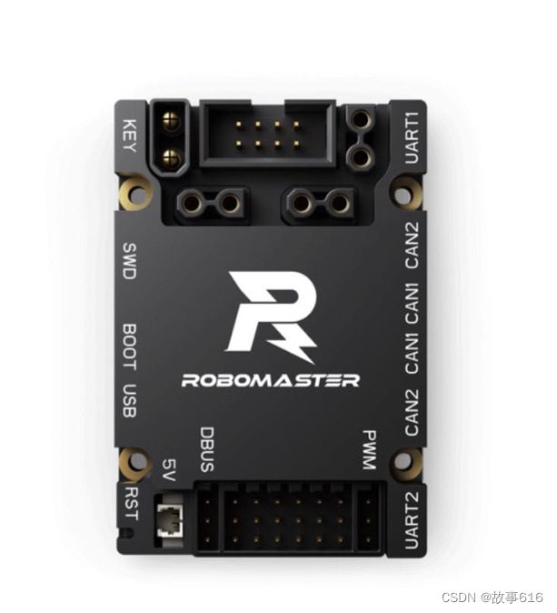
1、大疆c型开发板
我们可以从robomaster官网上下载c板的用户使用手册,在编写代码的时候用户开发手册往往非常重要。引脚配置、io说明等信息都可以从用户手册上获得。
2、gm6020电机
gm6020的说明手册也可以从robomaster的官网上下载,网址我会在下面给出。gm6020电机自带编码器,特点在于扭矩大,非常适合用来控制云台的航向和俯仰。
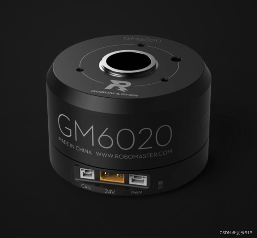
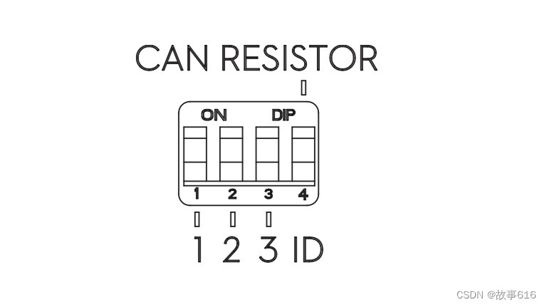
电机的id切换可以通过电机底下的拨码开关来设置,拨码开关有bit0、bit2、bit3三位,符合二进制编码,详细可见电机使用说明书
3、网址
二、代码编写
1、cubemx配置
(1)开启高速和速度外部时钟
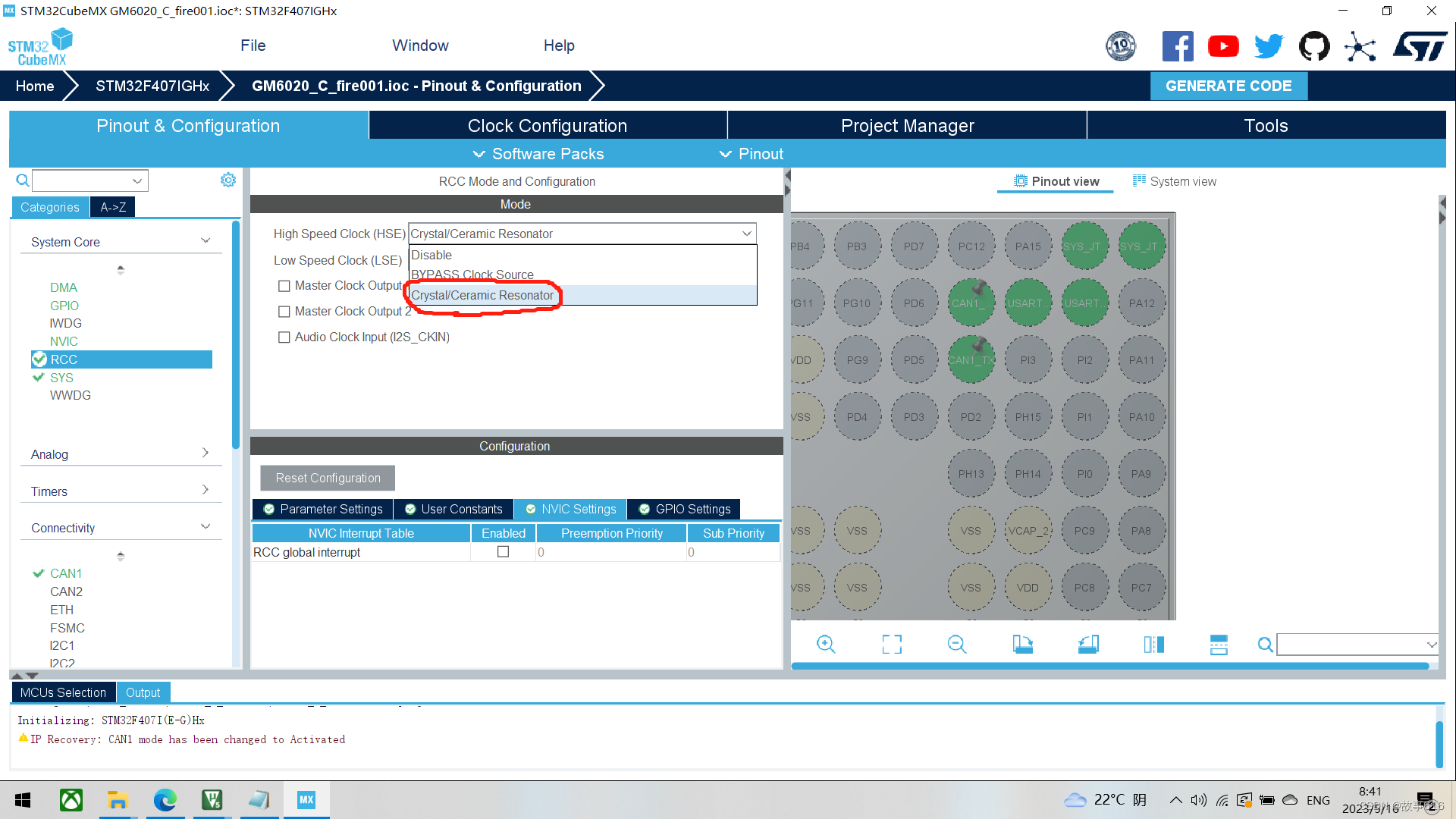
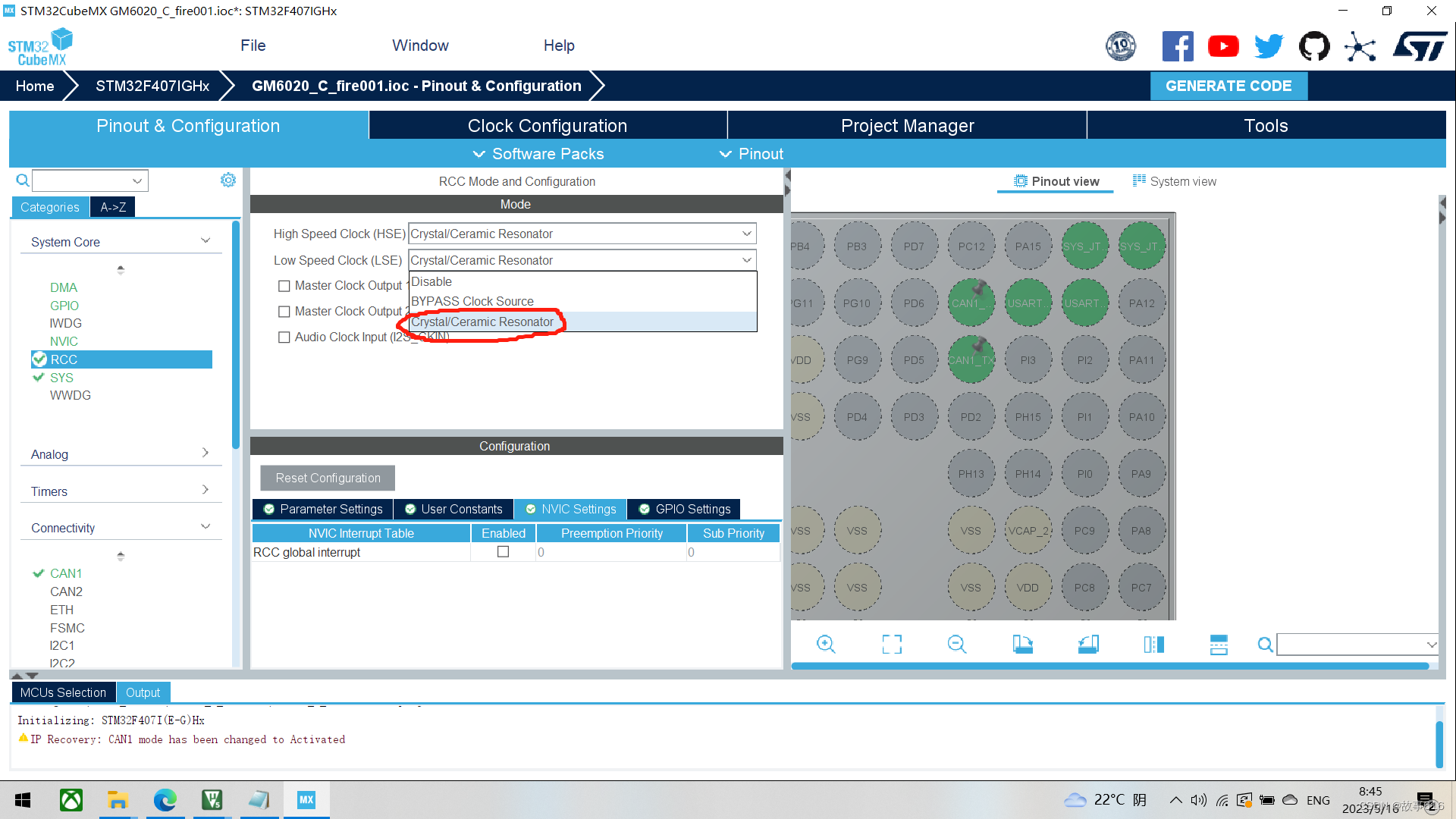
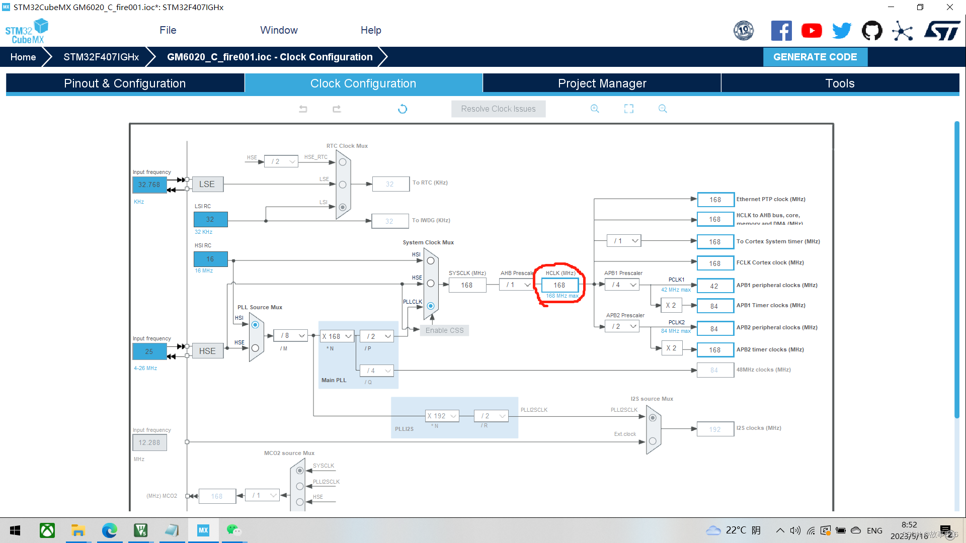
系统时钟设置为168mhz(最大为180mhz),设置为180mhz也是可以的
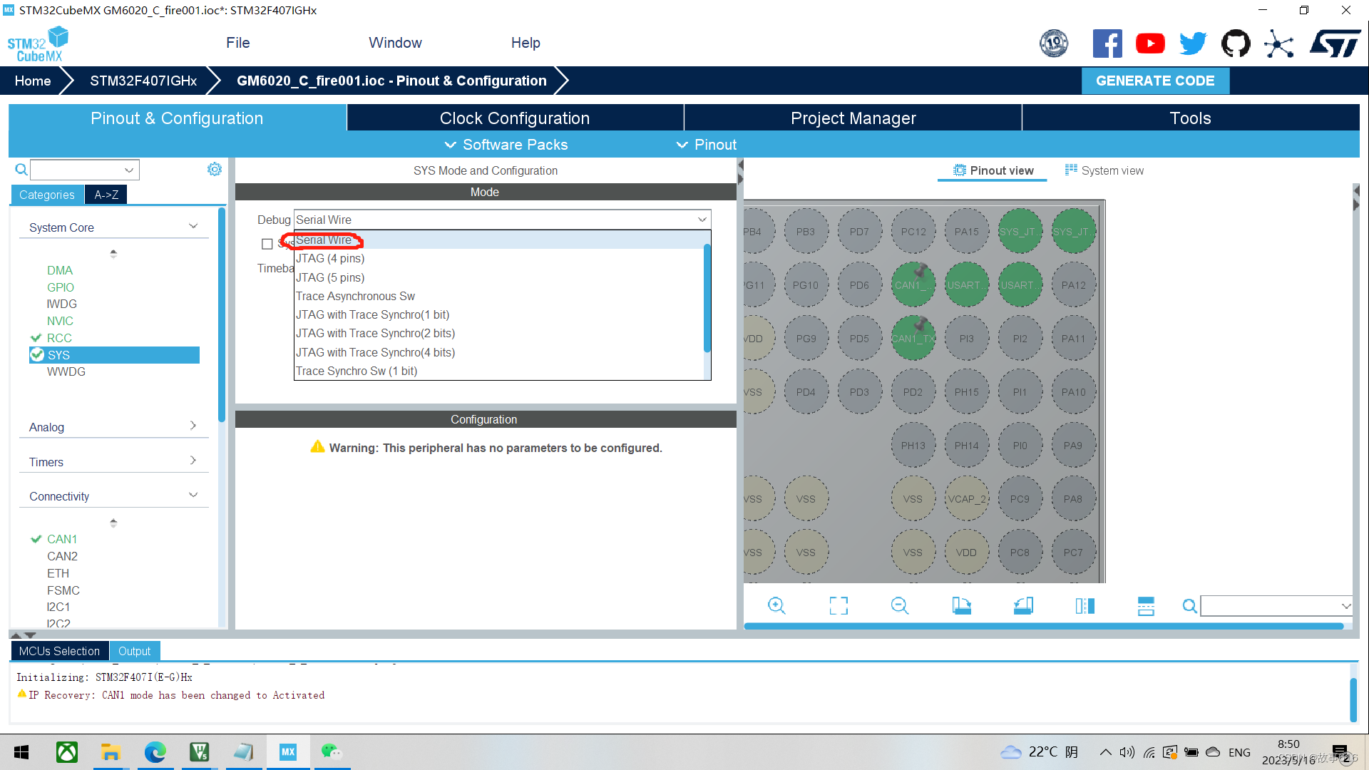
(2)debug设置成sw
(3)打开can1外设
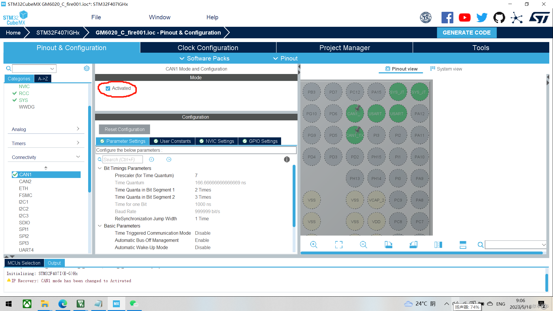
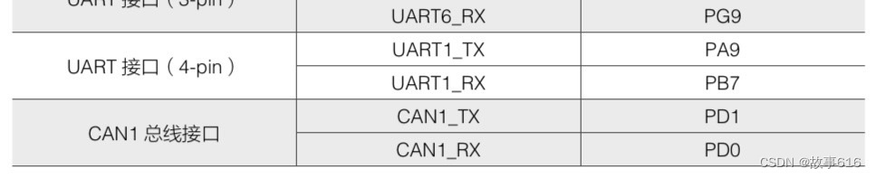
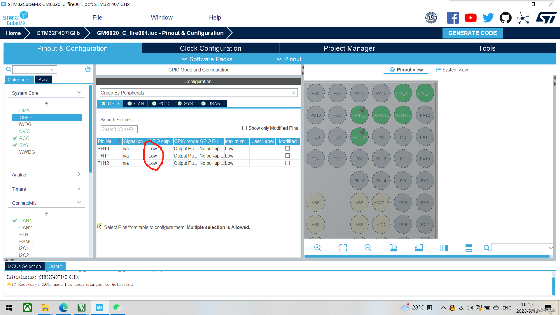
切记在打开can1外设时,cubemx会自动帮你配置,但当我们翻阅c板的使用手册,会发现can1的tx为pd1,rx为pd0,因此要自己重新配置引脚(这一点很重要!!!!!),如下图
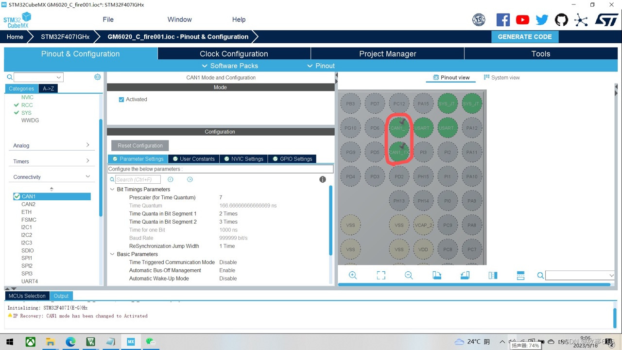
然后是配置can总线的传输速率,can总线接口最大支持1mhz的传输速率。我们可以将预分频器设置为7,bs1为2,bs2为3
br=42000000/7/(1+2+3)=1000000hz
其中42000000代表can1所挂载的apb1时钟的频率为42mhz
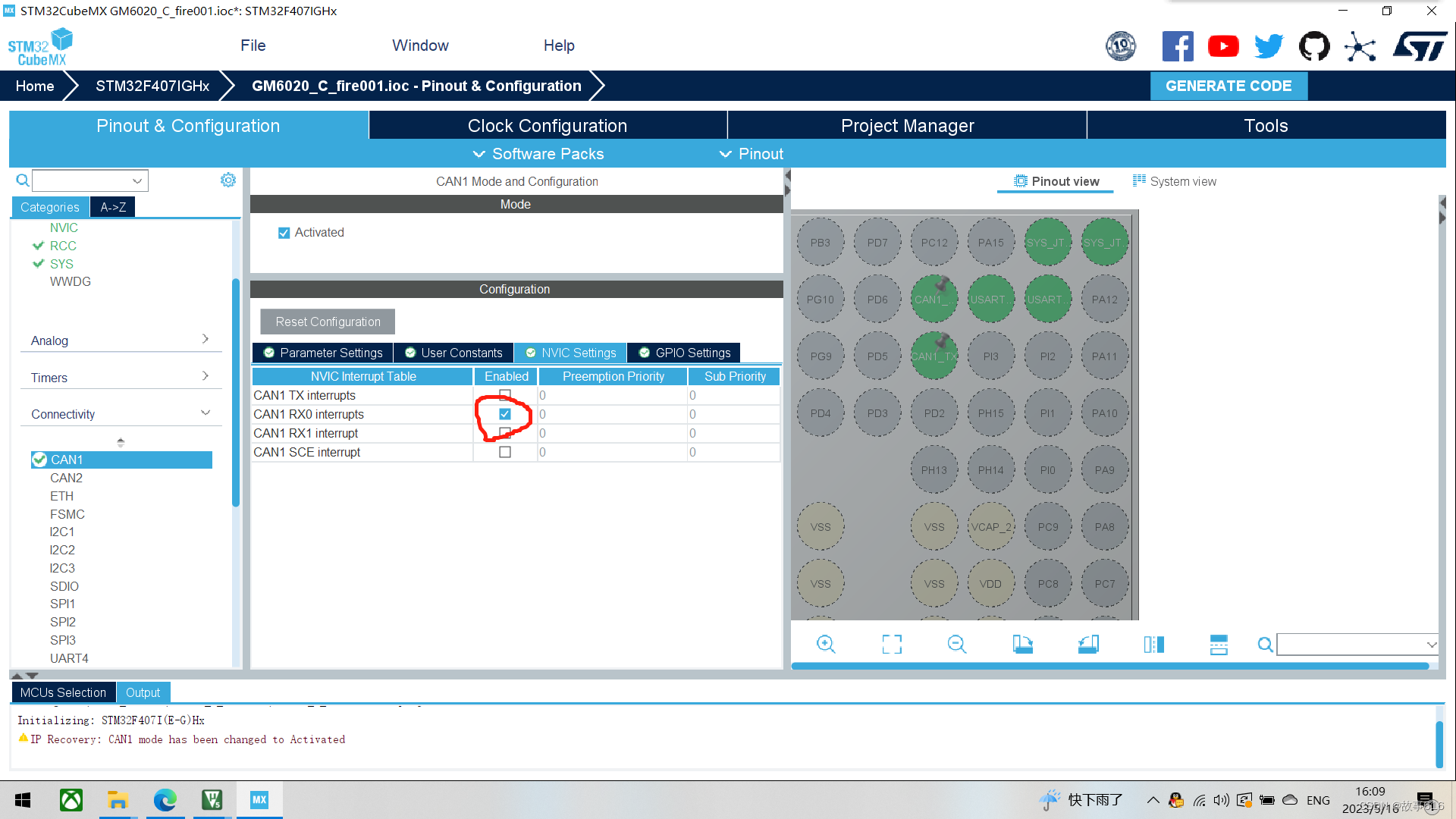
最后,不要忘了打开can1的接收(rx0)中断
(4)打开c板的红、绿、蓝指示灯,蓝灯引脚为ph10、绿灯ph11、红灯ph12,默认为高电平触发,所以初始状态设置为低电平。红绿蓝指示灯可以在调试的时候使用。
2、代码编写
bsp_can.h
在该头文件中,我们先创建用来储存电机信息的结构体motor_info_t,结构体内的内容也是参照6020电机的使用说明书,详细的大家可以自己去了解一下,如下两图
#ifndef __bsp_can_h_
#define __bsp_can_h_

#include "main.h"
#include "can.h"
#include "stm32f4xx.h"

typedef struct
{
    uint16_t can_id;//电机id
    int16_t  set_voltage;//设定的电压值
    uint16_t rotor_angle;//机械角度
    int16_t  rotor_speed;//转速
    int16_t  torque_current;//扭矩电流
    uint8_t  temp;//温度
}moto_info_t;

void can_filter_init(void);
void set_gm6020_motor_voltage(can_handletypedef* hcan,int16_t v1);

#endif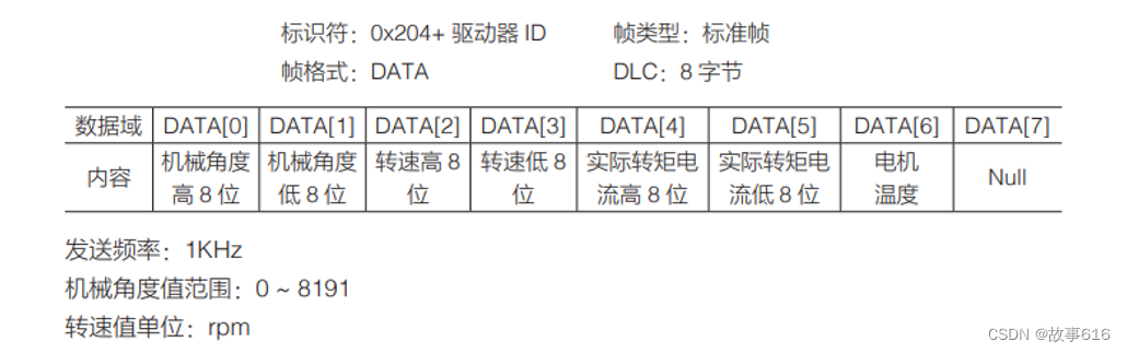
bsp_can.c
#include "bsp_can.h"

moto_info_t motor_yaw_info;
uint16_t can_cnt;

void can_filter_init(void)//筛选器配置
{
    can_filtertypedef can_filter_st;
    can_filter_st.filteractivation = enable;
    can_filter_st.filtermode = can_filtermode_idmask;
    can_filter_st.filterscale = can_filterscale_32bit;
    can_filter_st.filteridhigh = 0x0000;
    can_filter_st.filteridlow = 0x0000;
    can_filter_st.filtermaskidhigh = 0x0000;
    can_filter_st.filtermaskidlow = 0x0000;
    can_filter_st.filterbank = 0;
    can_filter_st.filterfifoassignment = can_rx_fifo0;
    hal_can_configfilter(&hcan1, &can_filter_st);
    hal_can_start(&hcan1);
    hal_can_activatenotification(&hcan1, can_it_rx_fifo0_msg_pending);

    can_filter_st.slavestartfilterbank = 14;
    can_filter_st.filterbank = 14;
    hal_can_configfilter(&hcan1, &can_filter_st);
    hal_can_start(&hcan1);
    hal_can_activatenotification(&hcan1, can_it_rx_fifo0_msg_pending);
}

void hal_can_rxfifo0msgpendingcallback(can_handletypedef *hcan)
{
  can_rxheadertypedef rx_header;
  uint8_t             rx_data[8];
  if(hcan->instance == can1)
  {
  hal_can_getrxmessage(hcan, can_rx_fifo0, &rx_header, rx_data); //receive can data
  switch(rx_header.stdid)
	{
	  case 0x205:
	{
    motor_yaw_info.rotor_angle    = ((rx_data[0] << 8) | rx_data[1]);
    motor_yaw_info.rotor_speed    = ((rx_data[2] << 8) | rx_data[3]);
    motor_yaw_info.torque_current = ((rx_data[4] << 8) | rx_data[5]);
    motor_yaw_info.temp           =   rx_data[6];
		break;
	}
	}
  }
}

void set_gm6020_motor_voltage(can_handletypedef* hcan,int16_t v1)
{
  can_txheadertypedef tx_header;
  uint8_t             tx_data[8] = {0};

  tx_header.stdid = 0x1ff;
  tx_header.ide   = can_id_std;
  tx_header.rtr   = can_rtr_data;
  tx_header.dlc   = 8;

  tx_data[0] = (v1>>8)&0xff;
  tx_data[1] =    (v1)&0xff;

  hal_can_addtxmessage(&hcan1, &tx_header, tx_data,(uint32_t*)can_tx_mailbox0);
}
can_filter_init()为筛选器配置函数,筛选器模式为32位掩码模式,显码为0x0000,掩码也是0x00000,也就是说这个函数的掩码掩了一个寂寞,这串代码的作用在于它其实没什么作用,但是如果不配置就无法完成通信,没什么用但一定要有。其次该函数还有初始化can的功能,要将它放在main.c当中
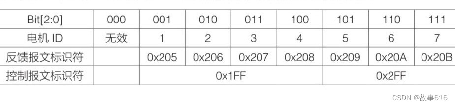
hal_can_rxfifo0msgpendingcallback(can_handletypedef *hcan)为can接收的中断回调函数,首先判断电机的id值(0x205就是gm6020电机的id1,详细可以参考官方手册),即识别是总线上的哪一个设备(电机)在发送信息,单片机接受来自该电机编码器的信息,如下图(机械角度、转速、转矩电流、温度)
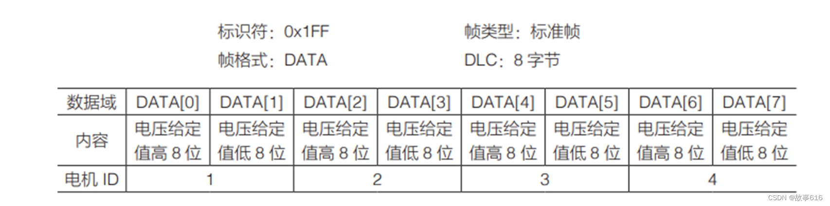
set_gm6020_motor_voltage(can_handletypedef* hcan,int16_t v1)为can的发送函数,首先识别数据的标识符是0x1ff(因为电机的id是1,所以其数据帧的标识符为0x1ff),然后主控发送电压值给电机,驱动电机转动。而发送给id1电机的电压值为数据帧的第1位和第二位(data[0]和data[1])

pid.h
该头文件中我们定义pid算法的结构体pid_struct_t
#ifndef __pid_h_
#define __pid_h_

#include "main.h"
#include "stm32f4xx.h"

typedef struct _pid_struct_t
{
  float kp;//比例
  float ki;//积分
  float kd;//微分
  float i_max;//积分限幅
  float out_max;//输出限幅

  float ref;      // target value目标角度
  float fdb;      // feedback value设定角度
  float err[2];   // error and last error差值

  float p_out;//比例输出
  float i_out;//积分输出
  float d_out;//微分输出
  float output;//pid总输出
}pid_struct_t;

void pid_init(pid_struct_t *pid,
              float kp,
              float ki,
              float kd,
              float i_max,
              float out_max);

void gimbal_pid_init(void);
float pid_calc(pid_struct_t *pid, float ref, float fdb);

#endif
pid.c
#include "pid.h"
pid_struct_t gimbal_yaw_speed_pid;
pid_struct_t gimbal_yaw_angle_pid;
void pid_init(pid_struct_t *pid,
float kp,
float ki,
float kd,
float i_max,
float out_max)//pid初始化函数
{
pid->kp = kp;
pid->ki = ki;
pid->kd = kd;
pid->i_max = i_max;
pid->out_max = out_max;
}
float pid_calc(pid_struct_t *pid, float ref, float fdb)//pid运算函数
{
pid->ref = ref;
pid->fdb = fdb;
pid->err[1] = pid->err[0];
pid->err[0] = pid->ref - pid->fdb;
pid->p_out = pid->kp * pid->err[0];
pid->i_out += pid->ki * pid->err[0];
pid->d_out = pid->kd * (pid->err[0] - pid->err[1]);
limit_min_max(pid->i_out, -pid->i_max, pid->i_max);
pid->output = pid->p_out + pid->i_out + pid->d_out;
limit_min_max(pid->output, -pid->out_max, pid->out_max);
return pid->output;
}
void gimbal_pid_init()//角度环和速度环的pid初始化,只是初测出来的数据,具体还需要测试
{
pid_init(&gimbal_yaw_speed_pid, 30, 0, 0, 30000, 30000);//p=30,i=0,d=0
pid_init(&gimbal_yaw_angle_pid, 400, 0, 0, 0, 320);//p=400,i=0,d=0
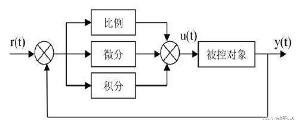
}该文件中我们运用双环pid控制电机的角度和转速,角度环为内环,计算出当前角度和我设定角度之间的差值;速度环为外环,如果检测出角度相差的值很大,就会输出一个大电压值,为使电机以更快的转速到达设定值,反之则输出小电压,小转速。
pid运算的逻辑图如下
mian.c
#include "main.h"
#include "can.h"
#include "dma.h"
#include "usart.h"
#include "gpio.h"

#include "bsp_can.h"
#include "pid.h"
#include "bsp_dbus.h"

int16_t led_cnt;
int16_t text_speed = 0;
int16_t target_yaw_speed;
float target_yaw_angle = 0;
float now_yaw_angle;
extern moto_info_t motor_yaw_info;
extern pid_struct_t gimbal_yaw_speed_pid;
extern pid_struct_t gimbal_yaw_angle_pid;


double msp(double x, double in_min, double in_max, double out_min, double out_max)//映射函数,将编码器的值(0~8191)转换为弧度制的角度值(-pi~pi)
{
	return (x-in_min)*(out_max-out_min)/(in_max-in_min)+out_min;
}


int main(void)
{

  hal_init();

  systemclock_config();

  mx_gpio_init();
  mx_dma_init();
  mx_can1_init();
  mx_usart3_uart_init();
  mx_usart1_uart_init();

  can_filter_init();//can初始化
  gimbal_pid_init();//pid初始化

  while (1)
  {

	led_cnt ++;
    if (led_cnt == 250)
    {
      led_cnt = 0;
      hal_gpio_togglepin(gpioh,gpio_pin_11); //blink cycle 500ms
    }

		now_yaw_angle=msp(motor_yaw_info.rotor_angle,0,8191,-pi,pi);//计算当前的编码器角度值,运用msp函数将编码器的值映射为弧度制

		pid_calc(&gimbal_yaw_angle_pid,target_yaw_angle, now_yaw_angle);//角度环
		pid_calc(&gimbal_yaw_speed_pid,gimbal_yaw_angle_pid.output, motor_yaw_info.rotor_speed);//速度环

		set_gm6020_motor_voltage(&hcan1,gimbal_yaw_speed_pid.output);//can发送函数,发送经过pid计算的电压值

		hal_delay(40);
		}

}
三、结束语
本人亲测代码是有效,但还是有很多地方需要改善,自己今年是第一年参加robomaster比赛,还有很多需要学习的地方。写这篇博客的契机在于希望对自己这段时间的学习进行总结,也希望将自己的一些经验分享出来,如果上述有什么不对或者不完善的地方也恳请大家批评指正
代码也参考csdn上很多好的文章,他们比我讲的更好
(6条消息) robomaster电机驱动_gm6020波特率_houena的博客-csdn博客
(6条消息) 【rm_ee_note】1 gm6020收发&简单的pid调试_gm6020控制角度_screepsjackeroo的博客-csdn博客
代码可直接使用。能控制6020电机转动到既定的角度值。


发表评论