一、知识点
1. pid是什么?
在pid控制中,p、i、d分别代表比例(proportional)、积分(integral)、微分(derivative)三个部分。它们是pid控制器中的三个调节参数,用于调节控制系统的输出,以使系统的反馈与期望值更加接近。
p(比例)部分:根据当前偏差的大小来调节输出。当偏差较大时,p部分的作用就越强烈,输出的变化也就越大。p控制项对应于系统的当前状态,它的作用是减小系统对设定值的超调和稳定时间。
i(积分)部分:对偏差的积累进行调节。它的作用是消除稳态误差,使系统更快地达到稳定状态。i控制项对应于系统过去的行为,它的作用是减小系统对外部干扰的影响。
d(微分)部分:根据偏差变化的速度来调节输出。它的作用是预测系统未来的行为,以减小系统的振荡和过冲现象,提高系统的响应速度和稳定性。
综合来说,pid控制器通过比例、积分、微分三个部分的组合来调节系统的输出,以实现对系统的精确控制。
2. 积分限幅–用于限制无限累加的积分项
因为积分系数的ki是与累计误差相乘的,所以效果是累加,随着时间的推移,积分项的值会升到很高,积分本来的作用是用来减小静态误差,但积分项过大会引起过大的震荡,所以我们可以加一个判断函数if,当积分项的值达到一定值后,就让积分项保持这个值,避免引起更大的震荡。
积分限幅的最大值,要根据经验实际多调试调试。
//为了防止积分项过度累积,引入积分项的限幅是一种常见的做法。
//限制积分项的幅值可以防止积分项过度增加,从而限制了系统的累积误差。这样可以避免系统过度响应或者不稳定。
float abs_limit(float value, float abs_max)   //积分限幅,设置最大值。
{
	if(value > abs_max)
		value = abs_max;

	if(value< -abs_max)
		value = -abs_max;
	return value;
}
3. 输出值限幅–用于任何pid的输出
这个需要查看产生pwm的定时器的计数周期初值设定。如motor_pwm_init(7200-1,0);,则outputmax就不能大于7200。
  //限制输出最大值,防止出现突发意外。输出outputmax的最大值
	if(pid->output > pid->outputmax )  pid->output = pid->outputmax;
	if(pid->output < - pid->outputmax )  pid->output = -pid->outputmax
4. pid工程
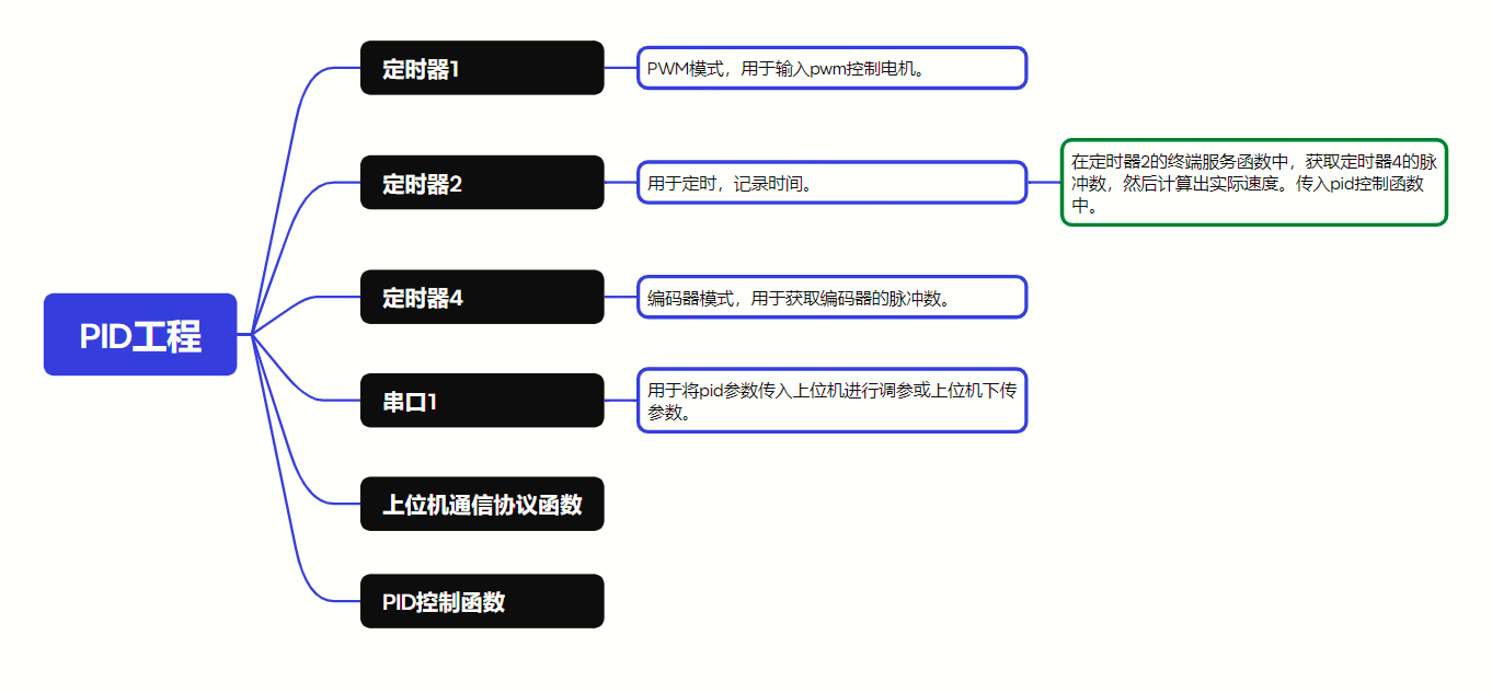
(1)定时器1(产生pwm)
tim1.c
#include "tim1.h"

void motor_pwm_init(u16 arr,u16 psc)
{
	gpio_inittypedef gpio_initstructure;
	tim_timebaseinittypedef  tim_timebasestructure;
	tim_ocinittypedef  tim_ocinitstructure;

	rcc_apb2periphclockcmd(rcc_apb2periph_tim1, enable);//
 	rcc_apb2periphclockcmd(rcc_apb2periph_gpioa , enable);  //使能gpio外设时钟使能

   //设置该引脚为复用输出功能,输出tim1 ch1 ch4的pwm脉冲波形
	gpio_initstructure.gpio_pin = gpio_pin_11; //tim_ch1 //tim_ch4
	gpio_initstructure.gpio_mode = gpio_mode_af_pp;  //复用推挽输出
	gpio_initstructure.gpio_speed = gpio_speed_50mhz;
	gpio_init(gpioa, &gpio_initstructure);

	tim_timebasestructure.tim_period = arr; //设置在下一个更新事件装入活动的自动重装载寄存器周期的值
	tim_timebasestructure.tim_prescaler =psc; //设置用来作为timx时钟频率除数的预分频值  不分频
	tim_timebasestructure.tim_clockdivision = 0; //设置时钟分割:tdts = tck_tim
	tim_timebasestructure.tim_countermode = tim_countermode_up;  //tim向上计数模式
	tim_timebaseinit(tim1, &tim_timebasestructure); //根据tim_timebaseinitstruct中指定的参数初始化timx的时间基数单位

	tim_ocinitstructure.tim_ocmode = tim_ocmode_pwm1; //选择定时器模式:tim脉冲宽度调制模式1
	tim_ocinitstructure.tim_outputstate = tim_outputstate_enable; //比较输出使能
	tim_ocinitstructure.tim_pulse = 0;                            //设置待装入捕获比较寄存器的脉冲值
	tim_ocinitstructure.tim_ocpolarity = tim_ocpolarity_high;     //输出极性:tim输出比较极性高
	tim_oc4init(tim1, &tim_ocinitstructure);  //根据tim_ocinitstruct中指定的参数初始化外设timx

    tim_ctrlpwmoutputs(tim1,enable);	//moe 主输出使能

	tim_oc4preloadconfig(tim1, tim_ocpreload_enable);  //ch4预装载使能

	tim_arrpreloadconfig(tim1, enable); //使能timx在arr上的预装载寄存器

	tim_cmd(tim1, enable);  //使能tim1
}
tim1.h
#ifndef __tim1_h
#define __tim1_h

#include <sys.h>
#define pwmb   tim1->ccr4  //pa11
void motor_pwm_init(u16 arr,u16 psc);

#endif
(2)定时器2(定时)
#include "tim2.h"
#include "led.h"
#include "usart.h"
#include "sys.h"

void motorcontrol(void)
{
 encoder_posion = read_position();//1.获取定时器3的编码器数值
 speed=posionpid_realize(&posionpid,encoder_posion);//2.输入位置式pid计算
 set_pwm(speed);  //3.pwm输出给电机
//指令/通道/发送数据/个数
 set_computer_value(send_fact_cmd, curves_ch2, &encoder_posion, 1);   /*4.给上位机通道2发送实际的电机速度值,详情看下面内容*/
}


void time2_init(u16 arr,u16 psc)
{
	tim_timebaseinittypedef tim_timebaseinitstructure;
	nvic_inittypedef nvic_initstructure;
	rcc_apb1periphclockcmd(rcc_apb1periph_tim2, enable);
	tim_internalclockconfig(tim2);


	tim_timebaseinitstructure.tim_clockdivision = tim_ckd_div1;
	tim_timebaseinitstructure.tim_countermode = tim_countermode_up;
	tim_timebaseinitstructure.tim_period = arr; //电机pwm频率要和定时器采样频率一致
	tim_timebaseinitstructure.tim_prescaler = psc;
	tim_timebaseinitstructure.tim_repetitioncounter = 0;
	tim_timebaseinit(tim2, &tim_timebaseinitstructure);

	tim_clearflag(tim2, tim_flag_update);
	tim_itconfig(tim2, tim_it_update, enable);

	nvic_prioritygroupconfig(nvic_prioritygroup_2);


	nvic_initstructure.nvic_irqchannel = tim2_irqn;
	nvic_initstructure.nvic_irqchannelcmd = enable;
	nvic_initstructure.nvic_irqchannelpreemptionpriority = 2;
	nvic_initstructure.nvic_irqchannelsubpriority = 1;
	nvic_init(&nvic_initstructure);

	tim_cmd(tim2, enable);
}

void tim2_irqhandler(void)
{
	if (tim_getitstatus(tim2, tim_it_update) == set)
	{
	    motorcontrol();
		tim_clearitpendingbit(tim2, tim_it_update);
	}
}
(3)定时器4(编码器)
#include "stm32f10x.h"                  // device header

void encoder_init(void)
{
	gpio_inittypedef gpio_initstructure;
	tim_timebaseinittypedef tim_timebaseinitstructure;
	tim_icinittypedef tim_icinitstructure;

	rcc_apb1periphclockcmd(rcc_apb1periph_tim4, enable);
	rcc_apb2periphclockcmd(rcc_apb2periph_gpiob, enable);

	gpio_initstructure.gpio_mode = gpio_mode_ipu;
	gpio_initstructure.gpio_pin = gpio_pin_6 | gpio_pin_7;
	gpio_initstructure.gpio_speed = gpio_speed_50mhz;
	gpio_init(gpiob, &gpio_initstructure);


	tim_timebaseinitstructure.tim_clockdivision = tim_ckd_div1;
	tim_timebaseinitstructure.tim_countermode = tim_countermode_up;
	tim_timebaseinitstructure.tim_period = 65536 - 1;		//arr
	tim_timebaseinitstructure.tim_prescaler = 1 - 1;		//psc
	tim_timebaseinitstructure.tim_repetitioncounter = 0;
	tim_timebaseinit(tim4, &tim_timebaseinitstructure);

	tim_icstructinit(&tim_icinitstructure);
	tim_icinitstructure.tim_channel = tim_channel_1;
	tim_icinitstructure.tim_icfilter = 0xf;

	tim_icinit(tim4, &tim_icinitstructure);
	tim_icinitstructure.tim_channel = tim_channel_2;
	tim_icinitstructure.tim_icfilter = 0xf;

	tim_icinit(tim4, &tim_icinitstructure);
	/*ti1和ti2都计数,上升沿计数*/
	tim_encoderinterfaceconfig(tim4, tim_encodermode_ti12, tim_icpolarity_rising, tim_icpolarity_rising);

	tim_cmd(tim4, enable);
}

int16_t read_position(void)
{
	int16_t temp;
	temp = tim_getcounter(tim4);  //获取定时器计数值
	tim_setcounter(tim4, 0);
	return temp;
}
(4)串口1
usart.c
#include "sys.h"
#include "usart.h"

#if system_support_os
#include "includes.h"					//ucos 使用
#endif

#if 1
#pragma import(__use_no_semihosting)
//标准库需要的支持函数
struct __file
{
	int handle;

};

file __stdout;
//定义_sys_exit()以避免使用半主机模式
void _sys_exit(int x)
{
	x = x;
}
//重定义fputc函数
int fputc(int ch, file *f)
{
	while((usart1->sr&0x40)==0);//循环发送,直到发送完毕
    usart1->dr = (u8) ch;
	return ch;
}
#endif


//串口1中断服务程序
//注意,读取usartx->sr能避免莫名其妙的错误
u8 usart_rx_buf[usart_rec_len];     //接收缓冲,最大usart_rec_len个字节.
//接收状态
//bit15,	接收完成标志
//bit14,	接收到0x0d
//bit13~0,	接收到的有效字节数目
u16 usart_rx_sta=0;       //接收状态标记

void uart_init(u32 bound){
  //gpio端口设置
	gpio_inittypedef gpio_initstructure;
	usart_inittypedef usart_initstructure;
	nvic_inittypedef nvic_initstructure;

	rcc_apb2periphclockcmd(rcc_apb2periph_usart1|rcc_apb2periph_gpioa, enable);	//使能usart1,gpioa时钟

	//usart1_tx   gpioa.9
	gpio_initstructure.gpio_pin = gpio_pin_9; //pa.9
	gpio_initstructure.gpio_speed = gpio_speed_50mhz;
	gpio_initstructure.gpio_mode = gpio_mode_af_pp;	//复用推挽输出
	gpio_init(gpioa, &gpio_initstructure);//初始化gpioa.9

	//usart1_rx	  gpioa.10初始化
	gpio_initstructure.gpio_pin = gpio_pin_10;//pa10
	gpio_initstructure.gpio_mode = gpio_mode_in_floating;//浮空输入
	gpio_init(gpioa, &gpio_initstructure);//初始化gpioa.10

	//usart1 nvic 配置
	nvic_initstructure.nvic_irqchannel = usart1_irqn;
	nvic_initstructure.nvic_irqchannelpreemptionpriority=3 ;//抢占优先级3
	nvic_initstructure.nvic_irqchannelsubpriority = 3;		//子优先级3
	nvic_initstructure.nvic_irqchannelcmd = enable;			//irq通道使能
	nvic_init(&nvic_initstructure);	//根据指定的参数初始化vic寄存器

	//usart 初始化设置

	usart_initstructure.usart_baudrate = bound;//串口波特率
	usart_initstructure.usart_wordlength = usart_wordlength_8b;//字长为8位数据格式
	usart_initstructure.usart_stopbits = usart_stopbits_1;//一个停止位
	usart_initstructure.usart_parity = usart_parity_no;//无奇偶校验位
	usart_initstructure.usart_hardwareflowcontrol = usart_hardwareflowcontrol_none;//无硬件数据流控制
	usart_initstructure.usart_mode = usart_mode_rx | usart_mode_tx;	//收发模式

	usart_init(usart1, &usart_initstructure); //初始化串口1
	usart_itconfig(usart1, usart_it_rxne, enable);//开启串口接受中断
	usart_cmd(usart1, enable);                    //使能串口1

}


void usart1_irqhandler(void)//串口中断服务函数
{
	 u8 res;
	if(usart_getitstatus(usart1, usart_it_rxne)== set ) //产生了接收中断
	{
		usart_clearitpendingbit(usart1,usart_it_rxne);  	//清除接收中断标志位
		res=usart_receivedata(usart1);
		protocol_data_recv(&res,1);
  }
}


void usart1_send(u8*data, u8 len)  //发送数据函数
{
	u8 i;
	for(i=0;i<len;i++)
	{
		while(usart_getflagstatus(usart1,usart_flag_tc)==reset);
		usart_senddata(usart1,data[i]);
	}
}
usart.h
#ifndef __usart_h
#define __usart_h
#include "stdio.h"
#include "sys.h"

#define usart_rec_len  			200  	//定义最大接收字节数 200
#define en_usart1_rx 			1		//使能(1)/禁止(0)串口1接收

extern u8  usart_rx_buf[usart_rec_len]; //接收缓冲,最大usart_rec_len个字节.末字节为换行符
extern u16 usart_rx_sta;         		//接收状态标记

void uart_init(u32 bound);
void usart1_send(u8*data, u8 len);
#endif
二、各类pid
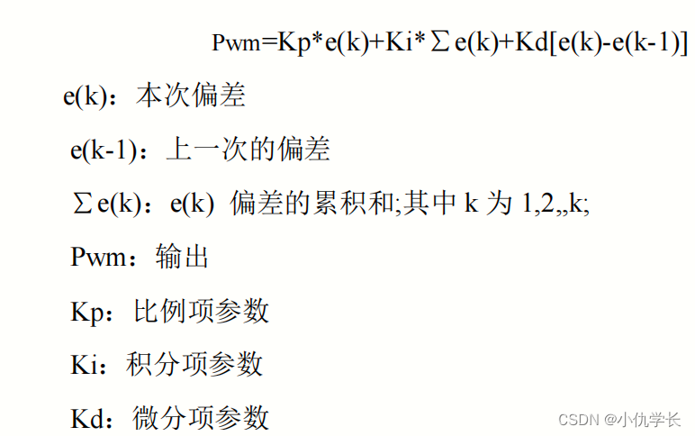
1. 位置式pid(用于位置环)
测量位置就是通过stm32去采集编码器的脉冲数据,通过脉冲计算出位置(角度)。目标位置和测量位置之间做差这个就是目前系统的偏差。送入 pid 控制器进行计算输出,然后再经过电机驱动的功率放大控制电机的转动去减小偏差, 最终达到目标位置的过程。
(1)公式
(2)代码
pid.c
typedef struct pid {
		float  kp;         //  proportional const  p系数
		float  ki;           //  integral const      i系数
		float  kd;         //  derivative const    d系数

		float  preverror ;          //  error[-2]
		float  lasterror;          //  error[-1]
		float  error;              //  error[0 ]
		float  derror;            //pid->error - pid->lasterror
		float  sumerror;           //  sums of errors

		float  output;

		float  integralmax;      //积分项的最大值
		float  outputmax;        //输出项的最大值
} pid;

//为了防止积分项过度累积,引入积分项的限幅是一种常见的做法。
//限制积分项的幅值可以防止积分项过度增加,从而限制了系统的累积误差。这样可以避免系统过度响应或者不稳定。
float abs_limit(float value, float abs_max)   //积分限幅,设置最大值。
{
	if(value > abs_max)
		value = abs_max;

	if(value< -abs_max)
		value = -abs_max;
	return value;
}


//函数里传入指针,修改时会修改指针里的值。
float pid_position_calc(pid *pid, float target_val, float actual_val)  //位置式pid
{

	pid->error = target_val - actual_val;      //与pid p系数相乘。比例误差值 当前差值=目标值-实际值
	pid->sumerror += pid->error;                 //与pid i系数相乘。稳态误差值 误差相加作为误差总和,给积分项
	pid->derror = pid->error - pid->lasterror;   //与pid d系数相乘。 微分项-消除震荡

	pid->output =   pid->kp* pid->error +
					abs_limit( pid->ki* pid->sumerror, pid->integralmax ) +
					pid->kd* pid->derror ;

   pid->lasterror = pid->error; //更新误差

  //限制输出最大值,防止出现突发意外。输出outputmax的最大值
	if(pid->output > pid->outputmax )  pid->output = pid->outputmax;
	if(pid->output < - pid->outputmax )  pid->output = -pid->outputmax;

	return pid->output ;   //输出为pwm值
}

//pid初始化
void pid_init(pid *pid, float kp , float ki , float kd , float limit_value)
{
	pid->kp= kp;
	pid->ki= ki;
	pid->kd= kd;

	pid->preverror =pid->lasterror = pid->error =pid->sumerror= pid->output =  0;
	pid->integralmax = pid->outputmax  = limit_value;
}
使用代码
#include "sys.h"

pid postion_pid;
float encoder_speed =0;
float position =0;
float speed=0;
float target_val =500;

int main()
{
	time2_init(10000-1,7200-1); //定时器2用于定时 10000*7200/72 = 1s
	encoder_init();  //定时器4的编码器
	motor_pwm_init(7200-1,0); //定时器1,初始化pwm输出
	pid_init(&postion_pid, 1.0, 0, 1.0, 7000);

	while(1)
	{

	}
}

//---- 获得电机的脉冲
int16_t encoder_get(void)
{
	int16_t temp;
	temp = tim_getcounter(tim4); //获取编码器当前值
	tim_setcounter(tim4, 0);  //将编码器计数器清0
	return temp;
}

//设置pwm
void set_pwm(int motor_pwm)
{
	tim_setcompare4(tim1, motor_pwm);
}

void motorcontrol(void)
{
	encoder_speed = encoder_get();//1.获取电机1s的脉冲数。即1s获取的脉冲数。即速度
	position +=encoder_speed ; //累计实际脉冲数。与时间无关。即总路程

	speed=pid_position_calc(&postion_pid, target_val , position);//2.输入增量式pid计算
	set_pwm(speed);  //3.pwm输出给电机
	//set_computer_value(send_fact_cmd, curves_ch2, &encoder_speed, 1);   /*4.给上位机通道2发送实际的电机速度值*/
}


void tim2_irqhandler(void)  //定时器中断函数,1s进一次中断
{
	if (tim_getitstatus(tim2, tim_it_update) == set)
	{
		motorcontrol();
		tim_clearitpendingbit(tim2, tim_it_update);
	}
}
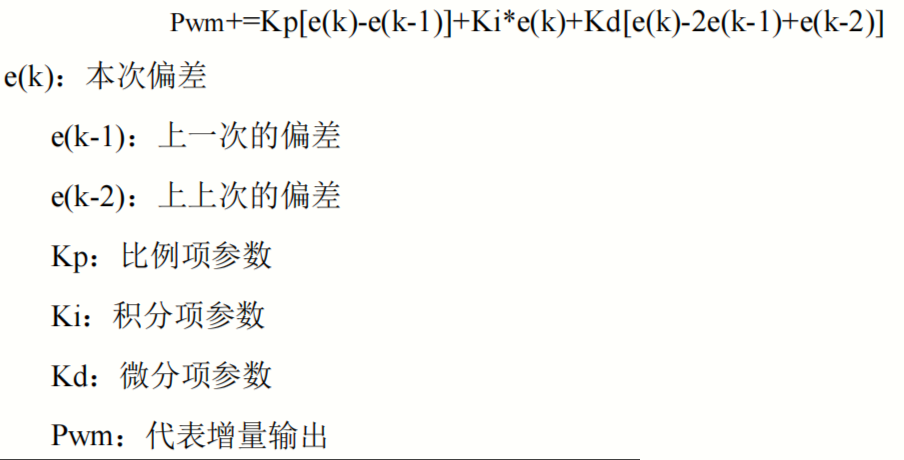
2. 增量式pid(用于速度环)
增量式pid也称速度环pid,速度闭环控制就是根据单位时间获取的脉冲数测量电机的速度信息,并与目标值进行比较,得到控制偏差,然后通过对偏差的比例、积分、微分进行控制,使偏差趋向于零的过程。
(1)公式
(2)代码
typedef struct pid {
		float  kp;         //  proportional const  p系数
		float  ki;           //  integral const      i系数
		float  kd;         //  derivative const    d系数

		float  preverror ;          //  error[-2]
		float  lasterror;          //  error[-1]
		float  error;              //  error[0 ]
		float  derror;            //pid->error - pid->lasterror
		float  sumerror;           //  sums of errors

		float  output;

		float  integralmax;      //积分项的最大值
		float  outputmax;        //输出项的最大值
} pid;


float pid_incremental_calc(pid *pid, float target_val, float actual_val)
{
	pid->error = target_val- actual_val;

	pid->output  +=  pid->kp* ( pid->error - pid->lasterror )+
					 pid->ki* pid->error +
					 pid->kd* ( pid->error +  pid->preverror - 2*pid->lasterror);

	pid->preverror = pid->lasterror;
	pid->lasterror = pid->error;

	if(pid->output > pid->outputmax )    pid->output = pid->outputmax;
	if(pid->output < - pid->outputmax )  pid->output = -pid->outputmax;

	return pid->output ;   //输出为pwm值
}

//pid初始化
void pid_init(pid *pid, float kp , float ki , float kd , float limit_value)
{
	pid->kp= kp;
	pid->ki= ki;
	pid->kd= kd;

	pid->preverror =pid->lasterror = pid->error =pid->sumerror= pid->output =  0;
	pid->integralmax = pid->outputmax  = limit_value;
}
(3)使用代码
#include "sys.h"

pid speedpid;
float encoder_speed =0;
float target_val =500;  //目标1s的脉冲数
float speed=0;//实际速度


int main()
{
	time2_init(10000-1,7200-1); //定时器2用于定时 10000*7200/72 = 1s
	encoder_init();  //定时器4的编码器
	motor_pwm_init(7200-1,0); //定时器1,初始化pwm输出
	pid_init(&speedpid, 1.0, 0, 1.0, 7000);

	while(1)
	{

	}
}

//获得电机的脉冲
int16_t encoder_get(void)
{
	int16_t temp;
	temp = tim_getcounter(tim4); //获取编码器当前值
	tim_setcounter(tim4, 0);  //将编码器计数器清0
	return temp;
}

//设置pwm
void set_pwm(int motor_pwm)
{
	tim_setcompare4(tim1, motor_pwm);
}

void motorcontrol(void)
{
	encoder_speed = encoder_get();//1.获取电机1s的脉冲数。即1s获取的脉冲数。即速度。
	speed=pid_incremental_calc(&speedpid,target_val ,encoder_speed);//2.输入增量式pid计算
	set_pwm(speed);  //3.pwm输出给电机
	//set_computer_value(send_fact_cmd, curves_ch2, &encoder_speed, 1);   /*4.给上位机通道2发送实际的电机速度值*/
}


void tim2_irqhandler(void)  //定时器中断函数,1s进一次中断
{
	if (tim_getitstatus(tim2, tim_it_update) == set)
	{
		motorcontrol();
		tim_clearitpendingbit(tim2, tim_it_update);
	}
}
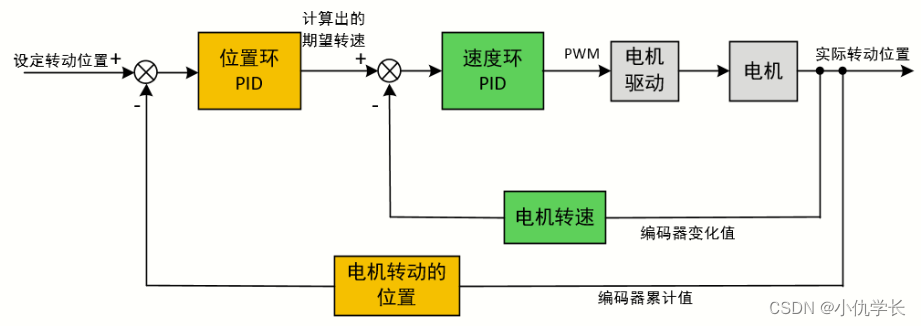
3. 串级pid
(1)位置环–速度环(用于控制电机)
利用位置式pid的方法将位置环和速度环组合在一起使用。位置环的输出作为速度环的输入。位置环的输出作为速度环的目标期望值。这意味着位置环的输出被视为速度环应该追踪的目标位置。速度环的任务是根据当前位置和目标位置之间的偏差来生成控制输出,使系统尽可能快地接近目标位置。速度环将根据当前速度和目标速度之间的差异来调整电机的输出,以便使实际速度接近目标速度。
简易代码
将目标位置和实际位置传入位置环pid中,计算出期望转速。然后通过期望转速与实际转速传入速度环pid中计算出对应的pwm,然后通过pwm去控制电机。
#include "stdio.h"

pid  postion_pid;
pid  speed_pid;

float encoder_speed =0;
float target_val =500;  //目标总的脉冲数
float speed=0;//实际速度
float position =0;

int main(void)
{

	  time2_init(10000-1,7200-1); //定时器2用于定时 10000*7200/72 = 1s,如果觉得时间太长可以缩短一些
	  encoder_init();  //定时器4的编码器
	  motor_pwm_init(7200-1,0); //定时器1,初始化pwm输出
	  // 初始化pid控制器
	  pid_init(&postion_pid, 1.0, 0.1, 0.01, 300); // pid参数根据实际情况调整
	  pid_init(&speed_pid, 1.0, 0.1, 0.01, 300);  // pid参数根据实际情况调整

	  while (1)
	  {

	  }
}

//获得电机的脉冲
int16_t encoder_get(void)
{
	int16_t temp;
	temp = tim_getcounter(tim4); //获取编码器当前值
	tim_setcounter(tim4, 0);  //将编码器计数器清0
	return temp;
}


//设置pwm
void set_pwm(int motor_pwm)
{
	tim_setcompare4(tim1, motor_pwm);
}


void motorcontrol(void)
{
	encoder_speed = encoder_get(); //1.获取电机1s的脉冲数。即1s获取的脉冲数。即速度
	position +=encoder_speed ;  //累计实际脉冲数。与时间无关。即总路程

	speed=pid_position_calc(&postion_pid, target_val , position);//2.输入位置式pid计算
	speed=pid_incremental_calc(&speedpid,speed, encoder_speed);//2.输入增量式pid计算
	set_pwm(speed);  //3.pwm输出给电机
	//set_computer_value(send_fact_cmd, curves_ch2, &encoder_speed, 1);   /*4.给上位机通道2发送实际的电机速度值*/
}


void tim2_irqhandler(void)  //定时器中断函数,1s进一次中断
{
	if (tim_getitstatus(tim2, tim_it_update) == set)
	{
		motorcontrol();
		tim_clearitpendingbit(tim2, tim_it_update);
	}
}
(2)位置环–位置环(用于控制舵机)
因为舵机没有编码器,无法获取实际速度,所以我们可以使用两个位置环来进行串级pid的使用,这样更加精准。两个位置环的实际值输入都为距离值。第一个位置环的输出作为第二个位置环的目标值输入。
实际举例:假设我们使用舵机来进行目标追踪。则第一个位置环的实际值输入:当前坐标-上次坐标的差值,目标值为0。将这两个值传入位置环计算的输出作为第二个位置环的目标值,第二个位置环的实际值可以传入:当前位置和摄像头中心点位置的差值。计算第二个位置环的输出。将其作为pwm值输入定时器通道去控制舵机。
三、调参
讲述kp、ki、kd的作用。
p:增加快速性,过大会引起震荡和超调,p单独作用会一直有静态误差。
i:减少静态误差,过大会引起震荡。
d:减小超调,过大会使响应速度变慢。
1. 知识点
(1)纯kp调节(比例)
假设有一个高为10m的水桶需要灌满水,这里我们假设kp=0.2(每次灌水量为剩余灌水量的0.2倍)。
第一次灌水:10×0.2, 剩余8(10-10×0.2)。
第二次灌水: 8×0.2, 剩余6.4(8-8×0.2)。
第三次灌水:6.4×0.2 ,剩余5.12。
…
这里我们发现当我们设置kp后,一直会慢慢接近目标值,但是永远不会到达目标值,这也就是会一直有静态误差。当kp设置过小时,消耗的时间也就会更多。这里我们可以适当的调大kp,使得更快的接近目标值。但是当kp大于某个定值时,就会出现抖动,如下,假设kp=1.5。
则第一次灌水:10×1.5,剩余 -5。
第二次灌水:-5×1.5,剩余2.5(-5 - (-5×1.5))。
第三次灌水:2.5×1.5,剩余 -1.25。
…
所以,要根据实际适当调整p值,不要使得kp过大,而出现抖动。
(2)ki调节(积分)
作用:积分时间用于解决系统的稳态误差问题,即系统无法完全到达期望值的情况。当存在稳态误差时,积分项会不断积累偏差,并且在一段时间内持续作用于控制器的输出,直到系统到达期望状态为止。
水桶例子:假设你在使用一个pid控制系统来控制一个水桶的水位。如果水桶的出水口略微大于水龙头的流量,那么水位就会慢慢下降,形成一个稳态偏差。积分时间就像是一个将稳态偏差中的水慢慢积累起来,直到水桶完全满了。如果积分时间设置得太大,可能会导致水桶溢出,而设置得太小则可能导致水桶永远无法完全填满。
(3)kd调节(微分)
作用:微分时间用于减小系统的超调和提高系统的稳定性。它通过监测偏差的变化速率来预测系统未来的行为,并相应地调整控制器的输出,以减少振荡和过冲现象。
水桶例子:继续以水桶控制系统为例,微分时间就像是观察水流速度的变化。如果你突然关闭水龙头,但是水桶的水位仍然在上升,那么微分项会告诉你要逐渐减小输出,以避免水位超过期望值。如果微分时间设置得太大,可能会导致系统对外部干扰过于敏感,反而引起不稳定性;而设置得太小,则可能无法有效地抑制超调和振荡。
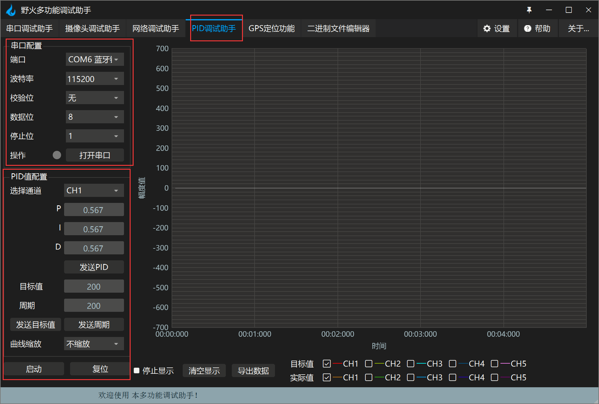
2. 调参软件–野火多功能调试助手
注意: 在串级pid控制中,上位机下传的pid参数通常应该是位置式的pid参数。因为在串级控制中,位置pid控制器的输出作为速度pid控制器的输入。因此,上位机通常会调节位置pid控制器的参数,以影响整个串级pid系统的行为。
当上位机调节位置pid参数时,它会直接影响到位置pid控制器的输出,从而间接地影响到速度pid控制器的输入,进而影响到整个系统的运行状态。因此,在串级pid控制中,上位机通常下传的是位置式的pid参数。
这个软件需要使用串口进行通信调参,下面是通信代码。
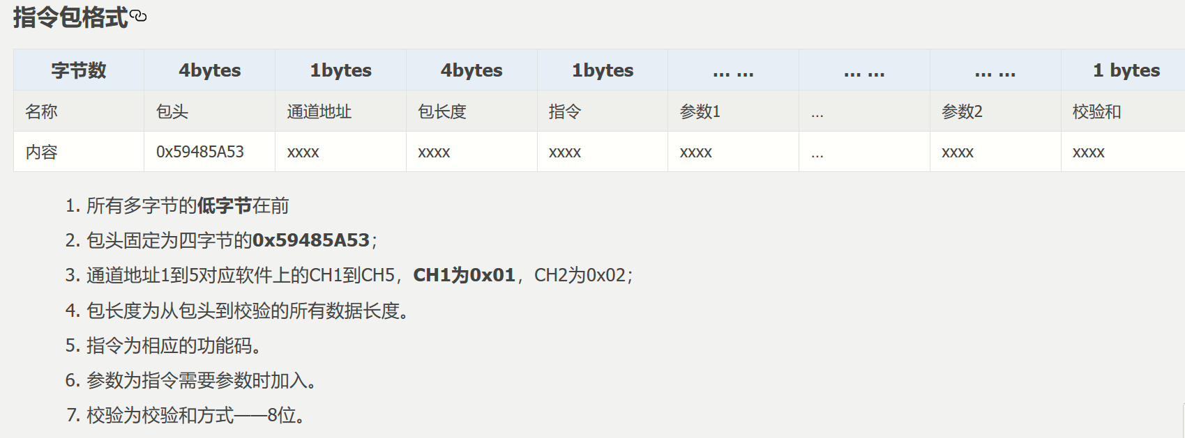
ⅰ. 传输格式
ⅱ. 协议解析代码
只需要先将protocol.c和protocol.h添加到工程中,然后使用相应的函数即可。切记:该代码需要和串口1代码搭配使用,因为使用了串口1的发送函数(见上面pid工程)。
protocol.c
/**
  ******************************************************************************
  * @file    protocol.c
  * @brief   野火pid调试助手通讯协议解析
  ******************************************************************************
  */
#include "protocol.h"
#include <string.h>
#include "pid.h"
#include "timer.h"

/*协议帧解析结构体*/
struct prot_frame_parser_t
{
    uint8_t *recv_ptr;         /*数据接收数组*/
    uint16_t r_oft;            /*读偏移*/
    uint16_t w_oft;            /*写偏移*/
    uint16_t frame_len;        /*帧长度*/
    uint16_t found_frame_head;
};

/*定义一个协议帧解析结构体*/
static struct prot_frame_parser_t parser;
/*定义一个接收缓冲区*/
static uint8_t recv_buf[prot_frame_len_recv];

/**
 * @brief   初始化接收协议
 * @param   void
 * @return  初始化结果.
 */
int32_t protocol_init(void)
{
	/*全局变量parser清空*/
    memset(&parser, 0, sizeof(struct prot_frame_parser_t));

    /* 初始化分配数据接收与解析缓冲区*/
    parser.recv_ptr = recv_buf;

    return 0;
}


/**
  * @brief 计算校验和
  * @param ptr:需要计算的数据
  * @param len:需要计算的长度
  * @retval 校验和
  */
uint8_t check_sum(uint8_t init, uint8_t *ptr, uint8_t len )
{
	/*校验和的计算结果*/
	uint8_t sum = init;

	while(len--)
	{
		sum += *ptr;/*依次累加各个数据的值*/
		ptr++;
	}

	return sum;
}

/**
 * @brief   获取帧类型(帧命令)
 * @param   *buf: 数据缓冲区
 * @param   head_oft: 帧头的偏移位置
 * @return  帧类型(帧命令)
 */
static uint8_t get_frame_type(uint8_t *buf, uint16_t head_oft)
{
	/*计算“帧命令”在帧数据中的位置*/
	uint16_t cmdindex = head_oft + cmd_index_val;

    return (buf[cmdindex % prot_frame_len_recv] & 0xff);
}

/**
 * @brief   获取帧长度
 * @param   *buf: 数据缓冲区
 * @param   head_oft: 帧头的偏移位置
 * @return  帧长度.
 */
static uint16_t get_frame_len(uint8_t *buf, uint16_t head_oft)
{
	/*计算“帧长度”在帧数据中的位置*/
	uint16_t lenindex = head_oft + len_index_val;

    return ((buf[(lenindex + 0) % prot_frame_len_recv] <<  0) |
            (buf[(lenindex + 1) % prot_frame_len_recv] <<  8) |
            (buf[(lenindex + 2) % prot_frame_len_recv] << 16) |
            (buf[(lenindex + 3) % prot_frame_len_recv] << 24));    // 合成帧长度
}

/**
 * @brief   获取crc-16校验值
 * @param   *buf:  数据缓冲区.
 * @param   head_oft: 帧头的偏移位置
 * @param   frame_len: 帧长
 * @return  校验值
 */
static uint8_t get_frame_checksum(uint8_t *buf, uint16_t head_oft, uint16_t frame_len)
{
	/*计算“校验和”在帧数据中的位置*/
	uint16_t crcindex = head_oft + frame_len - 1;

    return (buf[crcindex % prot_frame_len_recv]);
}

/**
 * @brief   查找帧头
 * @param   *buf:  数据缓冲区.
 * @param   ring_buf_len: 缓冲区大小(常量,如128)
 * @param   start: 起始位置(读偏移)
 * @param   len: 需要查找的长度
 * @return  -1:没有找到帧头,其他值:帧头的位置.
 */
static int32_t recvbuf_find_header(uint8_t *buf, const uint16_t ring_buf_len, uint16_t start, uint16_t len)
{
    uint16_t i = 0;

	/*帧头是4字节,从0查找到len-4,逐个比对*/
    for (i = 0; i < (len - 3); i++)
    {
        if (((buf[(start + i + 0) % ring_buf_len] <<  0) |
             (buf[(start + i + 1) % ring_buf_len] <<  8) |
             (buf[(start + i + 2) % ring_buf_len] << 16) |
             (buf[(start + i + 3) % ring_buf_len] << 24)) == frame_header) /*0x59485a53*/
        {
            return ((start + i) % ring_buf_len);
        }
    }
    return -1;
}

/**
 * @brief   计算未解析的数据的长度
 * @param   frame_len: 帧长度(数据中记录的帧长度)
 * @param   ring_buf_len: 缓冲区大小(常量,如128)
 * @param   start: 起始位置(读偏移)
 * @param   end: 结束位置(写偏移)
 * @return  未解析的数据长度
 */
static int32_t recvbuf_get_len_to_parse(uint16_t frame_len, const uint16_t ring_buf_len,uint16_t start, uint16_t end)
{
    uint16_t unparsed_data_len = 0; /*未解析的数据长度*/

	/*读偏移<=写偏移,说明数据在环形缓存区中是连续存储的*/
    if (start <= end)
	{
        unparsed_data_len = end - start;
	}
	/*否则,数据被分成了两部分,一部分在缓冲区结尾,一部分在缓冲区开头*/
    else
	{
		/*缓冲区结尾处的长度 + 缓冲区开头处处的长度*/
        unparsed_data_len = (ring_buf_len - start) + end;
	}

    if (frame_len > unparsed_data_len)
	{
		/*数据中记录的帧长度 > 未解析的数据长度*/
        return 0;
	}
    else
	{
        return unparsed_data_len;
	}
}

/**
 * @brief   接收数据写入缓冲区
 * @param   *buf:  数据缓冲区.
 * @param   ring_buf_len: 缓冲区大小(常量,如128)
 * @param   w_oft: 写偏移
 * @param   *data: 需要写入的数据
 * @param   data_len: 需要写入数据的长度
 * @return  void.
 */
 void recvbuf_put_data(uint8_t *buf, const uint16_t ring_buf_len, uint16_t w_oft, uint8_t *data, uint16_t data_len)
{
	/*要写入的数据超过了缓冲区尾*/
    if ((w_oft + data_len) > ring_buf_len)
    {
		/*计算缓冲区剩余长度*/
        uint16_t data_len_part = ring_buf_len - w_oft;

        /*数据分两段写入缓冲区*/
        memcpy((buf + w_oft), data, data_len_part); /*先将一部分写入缓冲区尾*/
        memcpy(buf, (data + data_len_part), (data_len - data_len_part));/*再将剩下的覆盖写入缓冲区头*/
    }
    else
	{
        memcpy(buf + w_oft, data, data_len);/*直接将整个数据写入缓冲区*/
	}
}

/**
 * @brief   协议帧解析
 * @param   *data: 返回解析出的帧数据
 * @param   *data_len: 返回帧数据的大小
 * @return  帧类型(命令)
 */
 uint8_t protocol_frame_parse(uint8_t *data, uint16_t *data_len)
{
    uint8_t frame_type = cmd_none;  /*帧类型*/
    uint16_t need_to_parse_len = 0; /*需要解析的原始数据的长度*/
    uint8_t checksum = 0;           /*校验和*/

	/*计算未解析的数据的长度*/
    need_to_parse_len = recvbuf_get_len_to_parse(parser.frame_len, prot_frame_len_recv, parser.r_oft, parser.w_oft);
    if (need_to_parse_len < 9)
	{
		/*数据太少,肯定还不能同时找到帧头和帧长度*/
        return frame_type;
	}

    /*还未找到帧头,需要进行查找*/
    if (0 == parser.found_frame_head)
    {
		int16_t header_oft = -1; /*帧头偏移*/

        /* 同步头为四字节,可能存在未解析的数据中最后一个字节刚好为同步头第一个字节的情况,
           因此查找同步头时,最后一个字节将不解析,也不会被丢弃*/
        header_oft = recvbuf_find_header(parser.recv_ptr, prot_frame_len_recv, parser.r_oft, need_to_parse_len);
        if (0 <= header_oft)
        {
            /* 已找到帧头*/
            parser.found_frame_head = 1;
            parser.r_oft = header_oft;

            /* 确认是否可以计算帧长*/
            if (recvbuf_get_len_to_parse(parser.frame_len, prot_frame_len_recv, parser.r_oft, parser.w_oft) < 9)
			{
                return frame_type;
			}
        }
        else
        {
            /* 未解析的数据中依然未找到帧头,丢掉此次解析过的所有数据*/
            parser.r_oft = ((parser.r_oft + need_to_parse_len - 3) % prot_frame_len_recv);
            return frame_type;
        }
    }

    /* 计算帧长,并确定是否可以进行数据解析*/
    if (0 == parser.frame_len)
    {
        parser.frame_len = get_frame_len(parser.recv_ptr, parser.r_oft);
        if(need_to_parse_len < parser.frame_len)
		{
            return frame_type;
		}
    }

    /* 帧头位置确认,且未解析的数据超过帧长,可以计算校验和*/
    if ((parser.frame_len + parser.r_oft - prot_frame_len_checksum) > prot_frame_len_recv)
    {
        /* 数据帧被分为两部分,一部分在缓冲区尾,一部分在缓冲区头 */
        checksum = check_sum(checksum, parser.recv_ptr + parser.r_oft, prot_frame_len_recv - parser.r_oft);
        checksum = check_sum(checksum, parser.recv_ptr, parser.frame_len - prot_frame_len_checksum + parser.r_oft - prot_frame_len_recv);
    }
    else
    {
        /* 数据帧可以一次性取完*/
        checksum = check_sum(checksum, parser.recv_ptr + parser.r_oft, parser.frame_len - prot_frame_len_checksum);
    }

    if (checksum == get_frame_checksum(parser.recv_ptr, parser.r_oft, parser.frame_len))
    {
        /* 校验成功,拷贝整帧数据 */
        if ((parser.r_oft + parser.frame_len) > prot_frame_len_recv)
        {
            /* 数据帧被分为两部分,一部分在缓冲区尾,一部分在缓冲区头*/
            uint16_t data_len_part = prot_frame_len_recv - parser.r_oft;
            memcpy(data, parser.recv_ptr + parser.r_oft, data_len_part);
            memcpy(data + data_len_part, parser.recv_ptr, parser.frame_len - data_len_part);
        }
        else
        {
            /* 数据帧可以一次性取完*/
            memcpy(data, parser.recv_ptr + parser.r_oft, parser.frame_len);
        }
        *data_len = parser.frame_len;
        frame_type = get_frame_type(parser.recv_ptr, parser.r_oft);

        /* 丢弃缓冲区中的命令帧*/
        parser.r_oft = (parser.r_oft + parser.frame_len) % prot_frame_len_recv;
    }
    else
    {
        /* 校验错误,说明之前找到的帧头只是偶然出现的废数据*/
        parser.r_oft = (parser.r_oft + 1) % prot_frame_len_recv;
    }
    parser.frame_len = 0;
    parser.found_frame_head = 0;

    return frame_type;
}

/**
 * @brief   接收到的数据写入缓冲区
 * @param   *data:  接收到的数据的数组.
 * @param   data_len: 接收到的数据的大小
 * @return  void.
 */
void protocol_data_recv(uint8_t *data, uint16_t data_len)
{
	/*数据写入缓冲区*/
    recvbuf_put_data(parser.recv_ptr, prot_frame_len_recv, parser.w_oft, data, data_len);

	/*计算写偏移*/
    parser.w_oft = (parser.w_oft + data_len) % prot_frame_len_recv;
}


/**
  * @brief 设置上位机的值
  * @param cmd:命令
  * @param ch: 曲线通道
  * @param data:参数指针
  * @param num:参数个数
  * @retval 无
  */
void set_computer_value(uint8_t cmd, uint8_t ch, void *data, uint8_t num)
{
	static packet_head_t set_packet;

	uint8_t sum = 0;    // 校验和
	num *= 4;           // 一个参数 4 个字节

	set_packet.head = frame_header;     // 包头 0x59485a53
	set_packet.ch   = ch;              // 设置通道
	set_packet.len  = 0x0b + num;      // 包长
	set_packet.cmd  = cmd;             // 设置命令

	sum = check_sum(0, (uint8_t *)&set_packet, sizeof(set_packet));       // 计算包头校验和
	sum = check_sum(sum, (uint8_t *)data, num);                           // 计算参数校验和

	usart1_send((uint8_t *)&set_packet, sizeof(set_packet));    // 发送数据头
	usart1_send((uint8_t *)data, num);                          // 发送参数
	usart1_send((uint8_t *)&sum, sizeof(sum));                  // 发送校验和
}

/**********************************************************************************************/
protocol.h
#ifndef __protocol_h__
#define __protocol_h__
/*****************************************************************************/
/* includes */
/*****************************************************************************/
#include "sys.h"
#include "usart.h"
#ifdef _cplusplus
extern "c" {
#endif
/* 数据接收缓冲区大小 */
#define prot_frame_len_recv 128
/* 校验数据的长度 */
#define prot_frame_len_checksum 1
/* 数据头结构体 */
typedef __packed struct
{
uint32_t head; // 包头
uint8_t ch; // 通道
uint32_t len; // 包长度
uint8_t cmd; // 命令
}packet_head_t;
#define frame_header 0x59485a53 // 帧头
/* 通道宏定义 */
#define curves_ch1 0x01
#define curves_ch2 0x02
#define curves_ch3 0x03
#define curves_ch4 0x04
#define curves_ch5 0x05
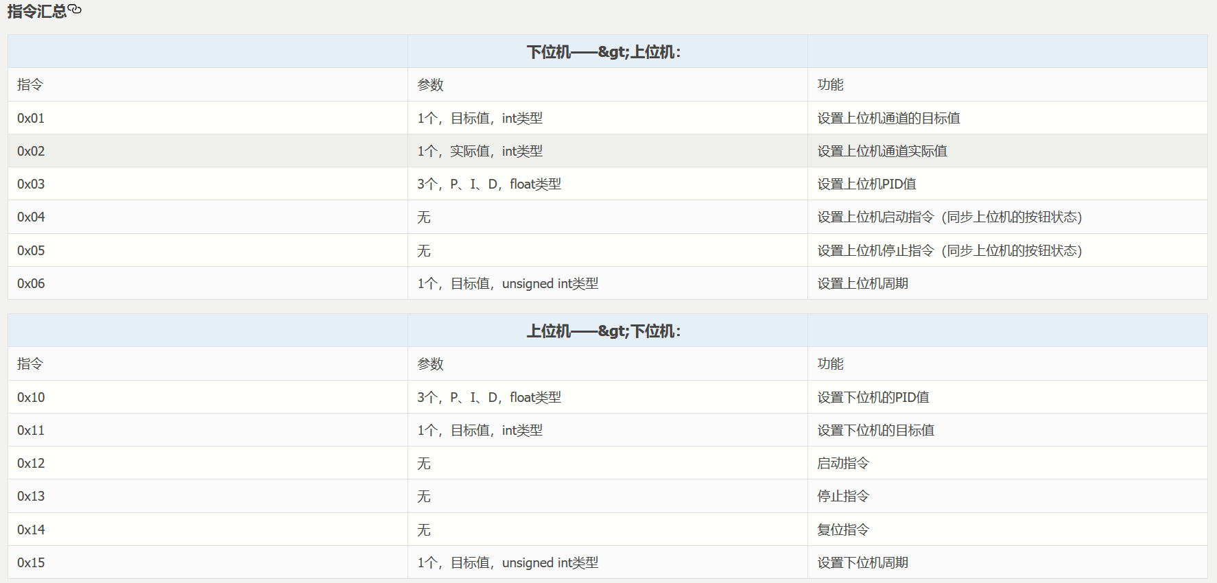
/* 指令(下位机 -> 上位机) */
#define send_target_cmd 0x01 // 发送上位机通道的目标值
#define send_fact_cmd 0x02 // 发送通道实际值
#define send_p_i_d_cmd 0x03 // 发送 pid 值(同步上位机显示的值)
#define send_start_cmd 0x04 // 发送启动指令(同步上位机按钮状态)
#define send_stop_cmd 0x05 // 发送停止指令(同步上位机按钮状态)
#define send_period_cmd 0x06 // 发送周期(同步上位机显示的值)
/* 指令(上位机 -> 下位机) */
#define set_p_i_d_cmd 0x10 // 设置 pid 值
#define set_target_cmd 0x11 // 设置目标值
#define start_cmd 0x12 // 启动指令
#define stop_cmd 0x13 // 停止指令
#define reset_cmd 0x14 // 复位指令
#define set_period_cmd 0x15 // 设置周期
/* 空指令 */
#define cmd_none 0xff // 空指令
/*********************************************************************************************
协议数据示例
1.下发目标值55:
|----包头----|通道|---包长度---|命令|----参数---|校验|
| 0 1 2 3 | 4 | 5 6 7 8| 9 |10 11 12 13| 14 | <-索引
|53 5a 48 59 | 01 | 0f 00 00 00| 11 |37 00 00 00| a6 | <-协议帧数
2.下发pid(p=1 i=2 d=3):
|----包头----|通道|---包长度---|命令|---参数p---|---参数i---|---参数d---|校验|
| 0 1 2 3 | 4 | 5 6 7 8| 9 |10 11 12 13|14 15 15 17|18 19 20 21| 22 | <-索引
|53 5a 48 59 | 01 | 17 00 00 00| 10 |00 00 80 3f|00 00 00 40|00 00 40 40| f5 | <-协议帧数
**********************************************************************************************/
/* 索引值宏定义 */
#define head_index_val 0x3u // 包头索引值(4字节)
#define chx_index_val 0x4u // 通道索引值(1字节)
#define len_index_val 0x5u // 包长索引值(4字节)
#define cmd_index_val 0x9u // 命令索引值(1字节)
/* 交换高低字节(未用到) */
#define exchange_h_l_bit(data) ((((data) << 24) & 0xff000000) |\
(((data) << 8) & 0x00ff0000) |\
(((data) >> 8) & 0x0000ff00) |\
(((data) >> 24) & 0x000000ff))
/* 合成为一个字 */
#define compound_32bit(data) (((*(data-0) << 24) & 0xff000000) |\
((*(data-1) << 16) & 0x00ff0000) |\
((*(data-2) << 8) & 0x0000ff00) |\
((*(data-3) << 0) & 0x000000ff))
/**
* @brief 接收数据处理
* @param *data: 要计算的数据的数组.
* @param data_len: 数据的大小
* @return void.
*/
void protocol_data_recv(uint8_t *data, uint16_t data_len);
/**
* @brief 初始化接收协议
* @param void
* @return 初始化结果.
*/
int32_t protocol_init(void);
/**
* @brief 设置上位机的值
* @param cmd:命令
* @param ch: 曲线通道
* @param data:参数指针
* @param num:参数个数
* @retval 无
*/
void set_computer_value(uint8_t cmd, uint8_t ch, void *data, uint8_t num);
uint8_t protocol_frame_parse(uint8_t *data, uint16_t *data_len);
#ifdef _cplusplus
}
#endif
#endif
(1)上位机将pid参数发送给下位机
上位机通过串口发送设置的pid参数信息,我们通过串口接收,并解析出这些信息,然后设置到我们的pid上。
我们在对pid调参时,如果我们使用的串级pid,我们只需要调外层的pid参数即可,因为内层的目标值是外层的输出。所以调外层的pid就可以影响整个系统。假如我们有x的内外层pid和y的内外层pid时,我们应该先调一个,如先调x。当把x层的参数调好后,y的pid直接使用x一样的参数即可。如下所示:
注意:为了全局代码的一致性,我们不使用上位机调整目标值,如果需要修改目标值,我们直接在代码中修改即可。此文我们只使用上位机调整pid参数(外层–位置层)!
/*
#define set_p_i_d_cmd        0x10     // 设置 pid 值
#define set_target_cmd       0x11     // 设置目标值
#define start_cmd            0x12     // 启动指令
#define stop_cmd             0x13     // 停止指令
#define reset_cmd            0x14     // 复位指令
#define set_period_cmd       0x15     // 设置周期
*/
pid posionpid;
pid speedpid;

//该代码为串口接收上位机pid信息解析代码,直接复制使用即可。
void receiving_process(void)
{
	uint8_t frame_data[128];         // 要能放下最长的帧
	uint16_t frame_len = 0;          // 帧长度
	uint8_t cmd_type = cmd_none;     // 命令类型

		/*解析指令类型*/
		cmd_type = protocol_frame_parse(frame_data, &frame_len);

		switch (cmd_type)
		{
			/*空指令*/
			case cmd_none:
			{
				break;
			}

			/***************设置pid***************/
			case set_p_i_d_cmd:
			{
				/* 接收的4bytes的float型的pid数据合成为一个字 */
				uint32_t temp0 = compound_32bit(&frame_data[13]);
				uint32_t temp1 = compound_32bit(&frame_data[17]);
				uint32_t temp2 = compound_32bit(&frame_data[21]);

				/*uint32_t强制转换为float*/
				float p_temp, i_temp, d_temp;
				p_temp = *(float *)&temp0;
				i_temp = *(float *)&temp1;
				d_temp = *(float *)&temp2;

                /*设置pid*/
				set_pid(p_temp, i_temp, d_temp);
			}
			break;

			/**************设置目标值***************/
			case set_target_cmd:
			{
				/* 接收的4bytes的int型的数据合成为一个字 */
				int actual_temp = compound_32bit(&frame_data[13]);

				/*设置目标值*/
				set_pid_target((float)actual_temp);
			}
			break;

			/******************启动*****************/
			case start_cmd:
			{
				/*开启pid运算*/
				tim_cmd(tim2,enable); //使能定时器2
			}
			break;

			/******************停止*****************/
			case stop_cmd:
			{
				/*停止pid运算*/
				set_pwm(0);
				tim_cmd(tim2,disable); //关闭定时器2
			}
			break;

			case reset_cmd:
			{
				nvic_systemreset();          // 复位系统
			}
			break;
		}
}

//设置外层(位置层)的pid参数
void set_pid(float p, float i, float d)
{
	posionpid.kp = p;    // 设置比例系数 p
	posionpid.ki = i;    // 设置积分系数 i
	posionpid.kd = d;    // 设置微分系数 d
}

//设置目标值
void set_pid_target(float temp_val)
{
	postion_outerx.target_val = temp_val;    // 设置当前的目标值
}

//获取目标值
float get_pid_target(pid *pid)
{
  return pid->target_val;    // 获取当前的目标值
}


void usart1_irqhandler(void)//串口中断服务函数
{
	 u8 res;
	if(usart_getitstatus(usart1, usart_it_rxne)== set ) //产生了接收中断
	{
		usart_clearitpendingbit(usart1,usart_it_rxne);  	//清除接收中断标志位
		res=usart_receivedata(usart1);
		protocol_data_recv(&res,1);   //该函数的定义在protocol.c里面。
  }
}

//-------------------------放到主函数的while里。


int main()
{

   protocol_init();   //该函数的定义在protocol.c里面。
   while(1)
   {
 		receiving_process(); //一直解析处理接收到的数据。
   }

}
(2)发送实际值、目标值给上位机
发送目标值与实际值。这里的目标值和实际值是外层pid(位置层)的目标值和实际值。
/*
#define send_target_cmd 0x01 // 发送上位机通道的目标值
#define send_fact_cmd 0x02 // 发送通道实际值
#define send_p_i_d_cmd 0x03 // 发送 pid 值(同步上位机显示的值)
#define send_start_cmd 0x04 // 发送启动指令(同步上位机按钮状态)
#define send_stop_cmd 0x05 // 发送停止指令(同步上位机按钮状态)
#define send_period_cmd 0x06 // 发送周期(同步上位机显示的值)
#define curves_ch1 0x01
#define curves_ch2 0x02
#define curves_ch3 0x03
#define curves_ch4 0x04
#define curves_ch5 0x05
*/
pid posionpid;
pid speedpid;
int16_t encoder_speed =0;
int16_t position =0;
int16_t speed;//实际速度
int target_val=500;
void motorcontrol(void)
{
encoder_speed= read_position();//1.获取定时器3的编码器数值
position+=encoder_speed; //2.速度积分得到位置
speed=pid_position_calc(&posionpid, target_val, position);//3.输入位置式pid计算
speed= pid_incremental_calc(&speedpid, speed, encoder_speed);//4.输入速度式pid计算
set_pwm(speed); //4.pwm输出给电机
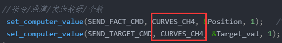
//指令/通道/发送数据/个数
set_computer_value(send_fact_cmd, curves_ch4, &position, 1); /*5.给上位机通道2发送实际的电机速度值*/
set_computer_value(send_target_cmd, curves_ch4, &target_val, 1); //发送目标值
}
void tim2_irqhandler(void)
{
if (tim_getitstatus(tim2, tim_it_update) == set)
{
motorcontrol();
tim_clearitpendingbit(tim2, tim_it_update);
}
}
int main()
{
pid_init(&posionpid, 1.0, 1.0, 1.0, 500);
pid_init(&speedpid,1.0, 1.0, 1.0, 500);
protocol_init(); //该函数的定义在protocol.c里面。
while(1)
{
}
}
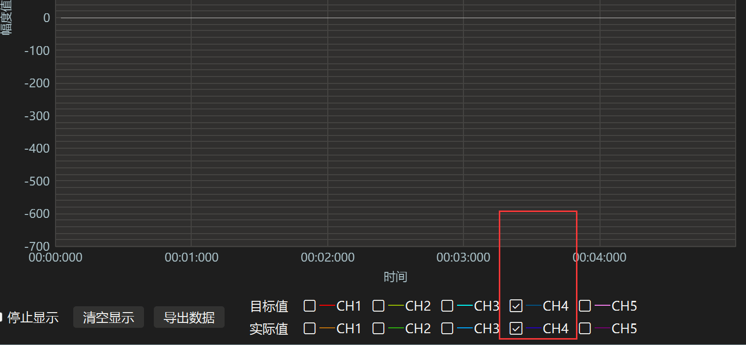
注意:如果上位机上不显示波形,一定要先关闭上位机重新打开才会显示!!且代码中我们将数据发送到通道4,所以我们在上位机上要使用通道4查看波形。

发表评论