目录
1.前言
这篇文章是为了填上一篇k210的简单pid巡线埋下的坑,k210和stm32通过串口通信,我是采用数据包的形式发送数据的,因为k210发送的数据有几种,采用数据包的形式发送比较安全。
本文代码运行的平台是stm32f103c8t6和k210 dock,只涉及到k210发送数据给stm32,stm32将接受到的数据显示到0.96寸oled屏上。
2.接线部分
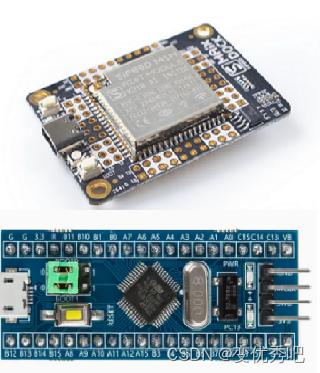
stm32使用串口外设是usart1,由于只接受数据所以只用到i/o的pa10;k210的串口通信i/o可以自行定义,我使用的是靠5v口近的gpio18。stm32上的3.3v电源和gnd分别k210上的5v电源和gnd连接。最后测试的时,直接用typ-c给k210供电,k210再给stm32供电。这个时候就有人会问了“为什么5v可以直接stm32供电?”因为一般的stm32f103c8t6最小系统上自带一块线性稳压器,它可以将k210的5v电源转化为3.3v给stm32芯片供电。(这只是为了方便测试,请检查你的stm32上是否有线性稳压器,若没有请单独供电)
| k210 tx发送 | stm32f103 rx接收 |
| gpio 18 | pa 10 |
| 5v | 3.3v |
| gnd | gnd |
3.代码部分
1.k210部分
1.调用自带的库文件
import time #延迟函数
from machine import uart #串口库函数
from fpioa_manager import fm # gpio重定向函数
2.将i/o18设置为uart1_tx功能并设置串口
fm.register(18, fm.fpioa.uart1_tx, force=true)
uart_a = uart(uart.uart1, 115200, 8, 0, 1, timeout=1000, read_buf_len=4096)
在使用 uart1 前,我们需要使用 fm 来对芯片引脚进行映射和管理,将 i/o 18 设置为 uart1 的发送引脚。
波特率设置为115200,这里注意要和stm32设置的一样。8位数据宽度,不需要奇偶校验位,1位停止位。
timeout 为串口接收超时时间。read_buf_len :串口接收缓冲,串口通过中断来接收数据,如果缓冲满了,将自动停止数据接收
3.数据发送函数
def sending_data(x,y,z):
    fh = bytearray([0x2c,0x12,x,y,z,0x5b])
uart_a.write(fh);传入你所需要发送的数据x、y、z,fh = bytearray([0x2c,0x12,x,y,z,0x5b])是将你的数据存入fh这个数组中。
uart_a.write用于使用串口发送数据,将这个数据包发送出去。
4.主函数
cx = 0
cy = 0
cz = 0
while true:
cx+=1;
cy+=1;
cz+=1;
sending_data(cx,cy,cz)
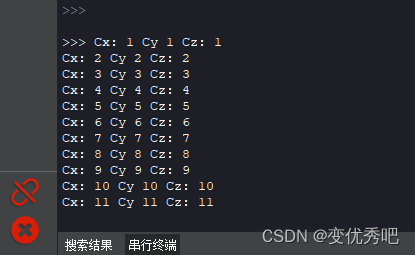
print("cx:",cx,"cy",cy,"cz:",cz)
time.sleep_ms(1000)该例子是让cx、cy、cz每一秒自加一并发送给stm32。
4.程序现象
程序运行后,串行终端每一秒打印一次
用一个ch340模块连接电脑读取一下串口数据。
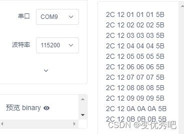
电脑可以成功接收每组6个的数据包,每组数据中不变的就是帧头的两个2c,12和帧尾的5b。知道了这个格式,那么我们就可以开始编写stm32上的代码了。
2.stm32部分
1主函数
本次程序在stm32上要实现的功能是接收数据后显示到oled上,只需要初始化oled和串口,在编写一下oled显示的代码就行了。
#include "stm32f10x.h"                  // device header
#include "oled.h"
#include "serial.h"
int main (void)
{
	oled_init();
	serial_init();
	oled_showstring(1,1,"cx:");
	oled_showstring(2,1,"cy:");
	oled_showstring(3,1,"cz:");
	while(1)
	{
		oled_shownum(1,4,cx,4);
		oled_shownum(2,4,cy,4);
		oled_shownum(3,4,cz,4);
	}

}
这里的cx、cy、cz我是直接在serial.h中使用了extern 外部变量声明。
2.串口接收程序
先进行串口初始化。
#include "stm32f10x.h"                  // device header

uint8_t cx,cy,cz;

void serial_init(void)
{
	rcc_apb2periphclockcmd(rcc_apb2periph_usart1, enable);
	rcc_apb2periphclockcmd(rcc_apb2periph_gpioa, enable);

	//usart1_rx	  pa10
	gpio_inittypedef gpio_initstructure;
	gpio_initstructure.gpio_mode = gpio_mode_ipu;
	gpio_initstructure.gpio_pin = gpio_pin_10;
	gpio_initstructure.gpio_speed = gpio_speed_50mhz;
	gpio_init(gpioa, &gpio_initstructure);

	usart_inittypedef usart_initstructure;
	usart_initstructure.usart_baudrate = 115200;
	usart_initstructure.usart_hardwareflowcontrol = usart_hardwareflowcontrol_none;
	usart_initstructure.usart_mode = usart_mode_rx;
	usart_initstructure.usart_parity = usart_parity_no;
	usart_initstructure.usart_stopbits = usart_stopbits_1;
	usart_initstructure.usart_wordlength = usart_wordlength_8b;
	usart_init(usart1, &usart_initstructure);

	usart_itconfig(usart1, usart_it_rxne, enable);

	nvic_prioritygroupconfig(nvic_prioritygroup_2);

	nvic_inittypedef nvic_initstructure;
	nvic_initstructure.nvic_irqchannel = usart1_irqn;
	nvic_initstructure.nvic_irqchannelcmd = enable;
	nvic_initstructure.nvic_irqchannelpreemptionpriority = 1;
	nvic_initstructure.nvic_irqchannelsubpriority = 1;
	nvic_init(&nvic_initstructure);

	usart_cmd(usart1, enable);
}使用的是usart1,它对应的接收引脚为pa10,将pa10设置为gpio_mode_ipu(输入上拉)模式,波特率设置为115200,8位数据宽度,不需要奇偶校验位,1位停止位,要和k210一致。再初始化串口中断并使能中断。
接收数据包的逻辑编写
void usart1_irqhandler(void)
{
		u8 com_data;
		u8 i;
		static u8 rxcounter1=0;
		static u16 rxbuffer1[6]={0};
		static u8 rxstate = 0;

		if( usart_getitstatus(usart1,usart_it_rxne)!=reset)  	   //接收中断
		{

				usart_clearitpendingbit(usart1,usart_it_rxne);   //清除中断标志
				com_data = usart_receivedata(usart1);
				if(rxstate==0&&com_data==0x2c)  //0x2c帧头
				{

					rxstate=1;
					rxbuffer1[rxcounter1++]=com_data;
				}

				else if(rxstate==1&&com_data==0x12)  //0x12帧头
				{
					rxstate=2;
					rxbuffer1[rxcounter1++]=com_data;
				}

				else if(rxstate==2)
				{
					rxbuffer1[rxcounter1++]=com_data;

					if(rxcounter1==6 && com_data == 0x5b)       //rxbuffer1接受满了,接收数据结束
					{

						cx=rxbuffer1[rxcounter1-4];
						cy=rxbuffer1[rxcounter1-3];
						cz=rxbuffer1[rxcounter1-2];
						rxcounter1 = 0;
						rxstate = 0;
					}
					else if(rxcounter1 > 6)            //接收异常
					{
						rxstate = 0;
						rxcounter1=0;
						for(i=0;i<6;i++)
						{
								rxbuffer1[i]=0x00;      //将存放数据数组清零
						}

					}
				}
				else   //接收异常
				{
						rxstate = 0;
						rxcounter1=0;
						for(i=0;i<6;i++)
						{
								rxbuffer1[i]=0x00;      //将存放数据数组清零
						}
				}

		}

}
com_data 用于读取stm32串口收到的数据,这个数据会被下一个数据掩盖,所以要将它用一个数组储存起来。
rxbuffer1[6]={0} 定义一个6个成员的数组,可以存放6个数据,刚好放下一个数据包。
rxcounter1 用来计次,让rxbufeer1这个数组能依次存入数据包。
rxstate 接收状态,判断程序应该接收第一个帧头、第二个帧头、数据或帧尾。
com_data = usart_receivedata(usart1); 读取 将串口接收到的数据。
当rxstate处于0时,为接收帧头1模式。若接收到帧头1(0x2c),将rxstate置1,切换到接收帧头2模式,并将帧头1存入rxbuffer1[0]的位置,rxcounter1加一。
当rxstate处于1时,为接收帧头2模式。若接收到帧头2(0x12),将rxstate置2,切换到保存数据模式,并将帧头2存入rxbuffer1[1]的位置,rxcounter1加一。
当rxstate处于2时,为保存数据模式。rxbuffer1[]将接收到的数据依次存入rxbuffer1[2]、rxbuffer1[3]、rxbuffer1[4]、rxbuffer1[5]中。当接收到第六位数据时,进行判断是否为帧尾(0x5b),若是帧尾分别保存数据rxbuffer1[2]、rxbuffer1[3]、rxbuffer1[4]到cx、cy、 cz中。
若是不是帧尾帧尾将会把rxstate、rxcounter1和rxbuffer1[]全部置零做接收异常处理。
若没接收到帧头1(0x2c)和帧头2(0x12),将会把rxstate、rxcounter1和rxbuffer1[]全部置零做接收异常处理。
3.程序现象
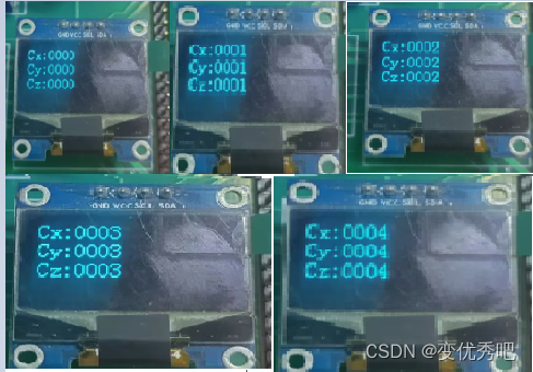
oled显示cx、cy、 cz每秒加一
4.完整代码
k210
# untitled - by: user - 周日 4月 23 2023
import time
from machine import uart #串口库函数
from fpioa_manager import fm # gpio重定向函数

fm.register(18, fm.fpioa.uart1_tx, force=true)
uart_a = uart(uart.uart1, 115200, 8, 0, 1, timeout=1000, read_buf_len=4096)


def sending_data(x,y,z):
    fh = bytearray([0x2c,0x12,x,y,z,0x5b])
    uart_a.write(fh);

cx = 0
cy = 0
cz = 0

while true:

    cx+=1;
    cy+=1;
    cz+=1;
    sending_data(cx,cy,cz)
    print("cx:",cx,"cy",cy,"cz:",cz)
    time.sleep_ms(1000)
stm32
 https://gitee.com/ad123zsg/electronic-game-code/tree/486edcd7466f0e19a2ecc559c43238f8af6af34b/%e4%b8%bb%e6%8e%a7/c8t6/k210%e4%b8%8estm32%e9%80%9a%e4%bf%a1
5.总结
目前已经讲述了stm32驱动a4950、k210的简单pid循迹,但要做出一辆循迹小车还是不够的,还需要pid速度环去调节小车的速度,才能完成一个完整的循迹小车,有时间我会更新后面的代码。

发表评论