写这个是为了记录学习过程,为了方便日后快速理解所以话比较通俗,当然也会有些许理解错误,欢迎各位大佬指正,小弟在此感激不尽
一、什么是无刷电机?
1、长什么样?
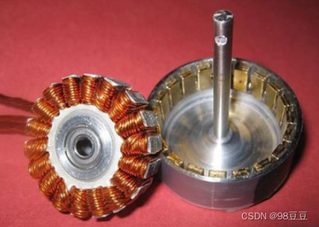
无刷无刷,跟有刷电机的区别就是有无电刷(电刷的作用是导电换向),在有刷电机中电刷会随着使用时间的增加逐渐磨损,所以寿命受限。
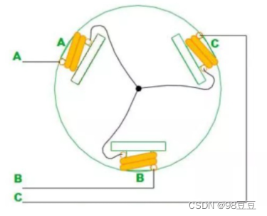
下图里面是一种无刷电机,无刷电机分两种:外转子、内转子。图中这种如果我没理解错,应该叫外转子无刷电机?应该是的(60%确定吧)。
2、怎么工作?
无刷电机与有刷电机不同,有刷电机是两根线(也就是一个直流电源)加合适的电压就可以转起来,而无刷电机是有三根线(a、b、c相)按照一定的规律才可以转起来。
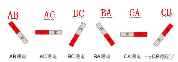
下图可表示无刷电机的简易驱动动画(在同一时间内有两根线通的,我觉着理解为三个有刷电机的驱动,一次只用两根线,用完了再换线),如果你手速够快,手动调整通电顺序,电机也可以转起来,但是你应该做不到速度那么快,所以尝尝采用mos管控制电路的切换。
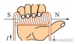
你需要知道怎么用右手螺旋定则判断磁场方向
根据右手螺旋定则(手心握着那个定子,四指是电流方向,大拇指方向为产生的磁场方向),判断在不同通电时刻下通电相(a、b、c)产生的磁场方向。
无刷电机中,三相星形联结的二导通方式最为常用,这里用该模型做简单分析:
当对a、b分别施加正负电压,根据上文提到的右手螺旋定则可推断出定子产生的磁极方向如下图的右边部分所示:
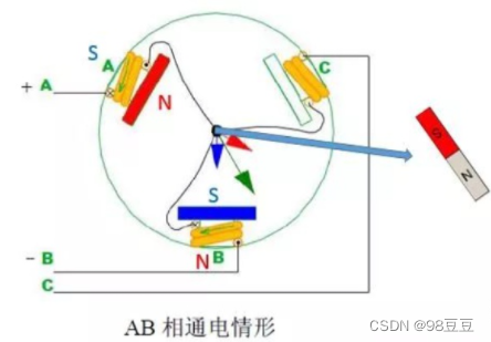
想象一下,在上面这个图中右边产生的这个磁场中,在中心点处随便放一块磁体(有n、s极),这个磁体最终的姿态应该是什么样的? 对,就是跟右边这个一样。 因为要保证这个磁场内的磁感应线方向是统一的,所以要一样。 那么如果这个随便放的磁铁是无刷电机的转子,那么这个转子就会转到这个位置,电机也就转了起来(理论上转了一丢丢)
接着,给a、c分别施加正负电压,分析产生的新磁场,看下图:
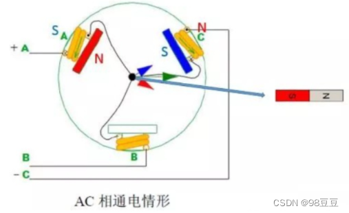
同理可得,转子会转到上图右边那样的位置。
继续,给b、c分别施加正负电压,分析产生的新磁场,看下图:
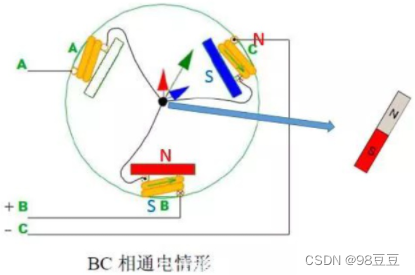
同理可得,转子会转到上图右边那样的位置。
…
…
依次推,可以得到6种通电状态下转子的位置角度,每个状态依次相差60度,6个过程完成了无刷电机的依次完整转动。
二、试着让它转起来
1、stm32cubemx配置
(1)新建工程:这一块老规矩,穷,所以用stm32f103c8t6这块板子了。
(2)配置相关功能
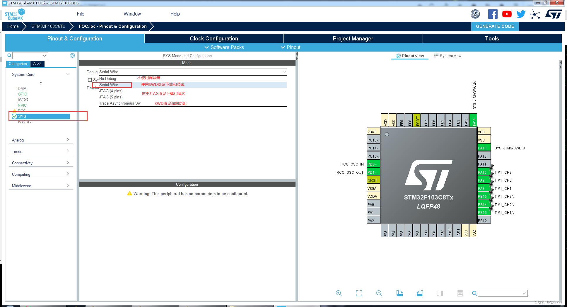
sys设置
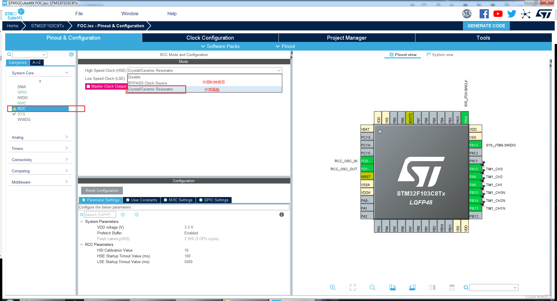
rcc设置
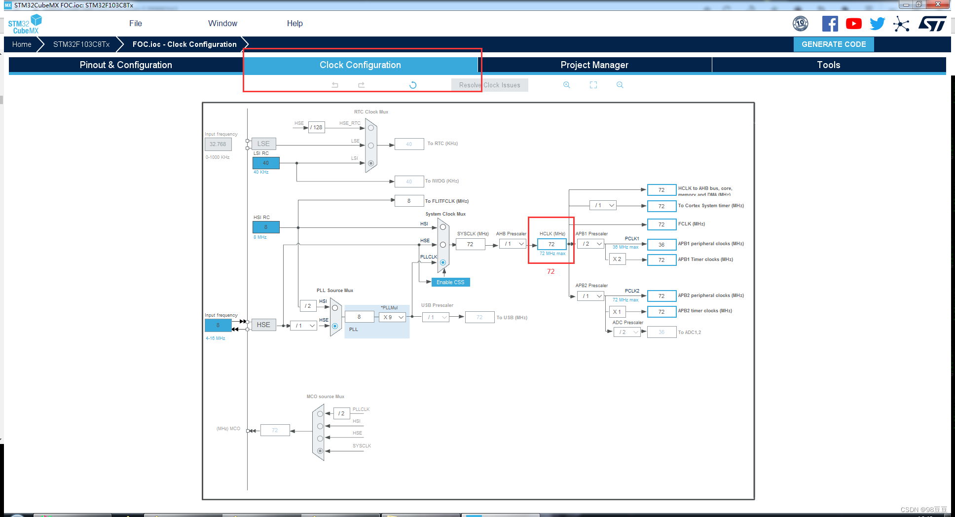
时钟树设置
关于时钟树这一块不清楚可看stm32基础知识(三)-- 系统时钟rcc详解这个文章。
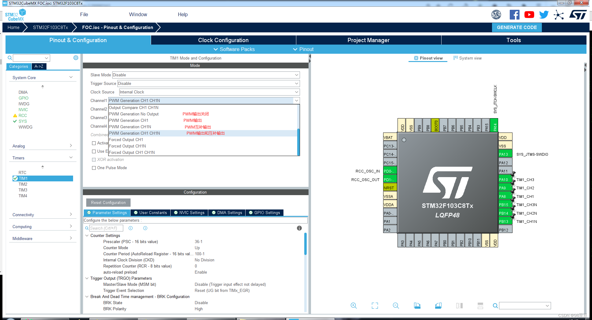
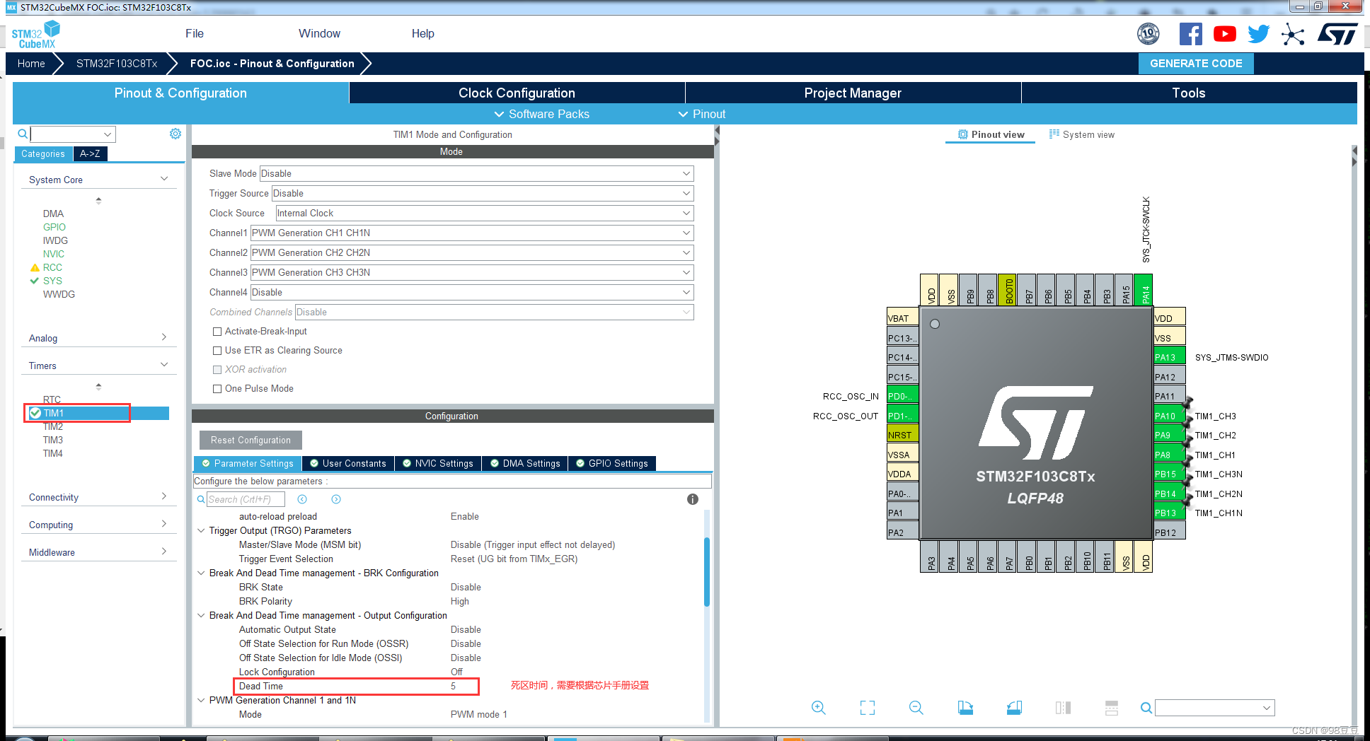
定时器tim1设置
因为要生成pwm信号,所以用定时器方便一点。此处用的tim1属于高级定时器,由apb2负责。
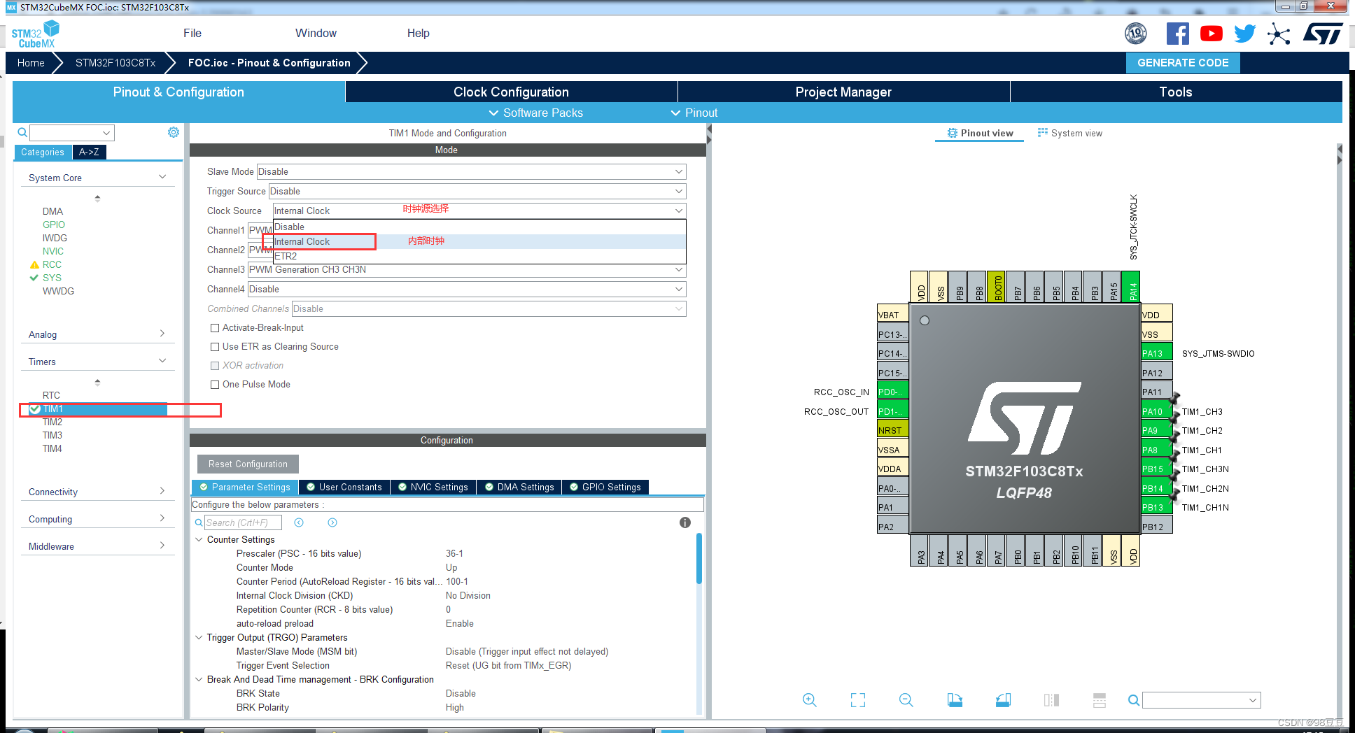
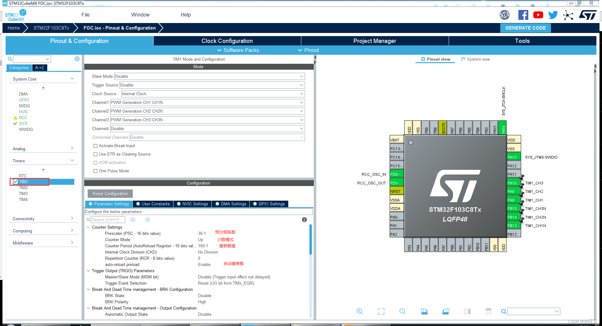
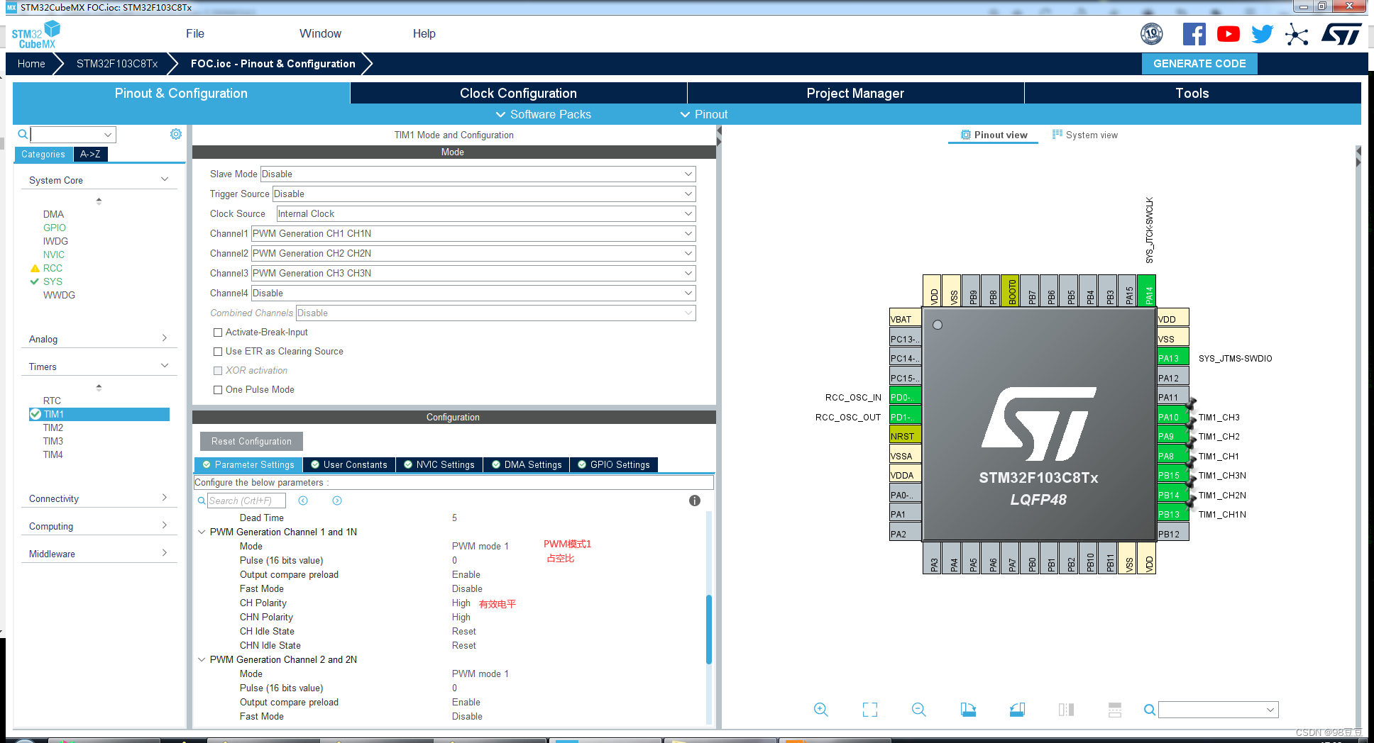
占空比在程序中进行设置,此处不设置占空比
工程输出设置
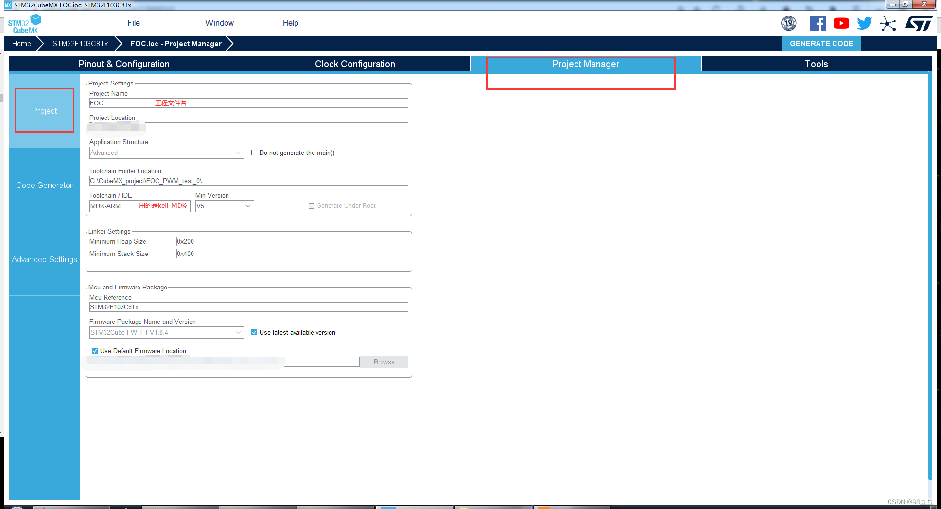
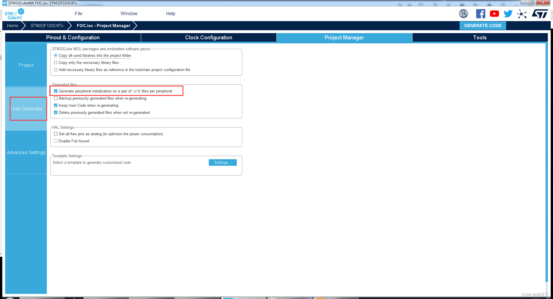
之后点击右上角的 generate code 生成工程文件。
2、keil/clion代码编写
在生成的工程文件下 mdk-arm 文件夹中点击后缀名为“.uvprojx”的文件打开工程。打开工程后先编译(保证工程代码正确)。如果出现下图情况
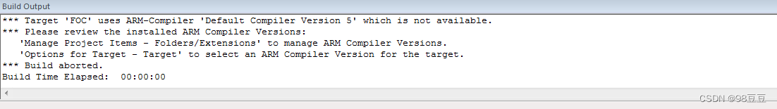
按照下图更改设置即可(好像是因为高级版本多了个啥,还是用老版本好一点感觉)。
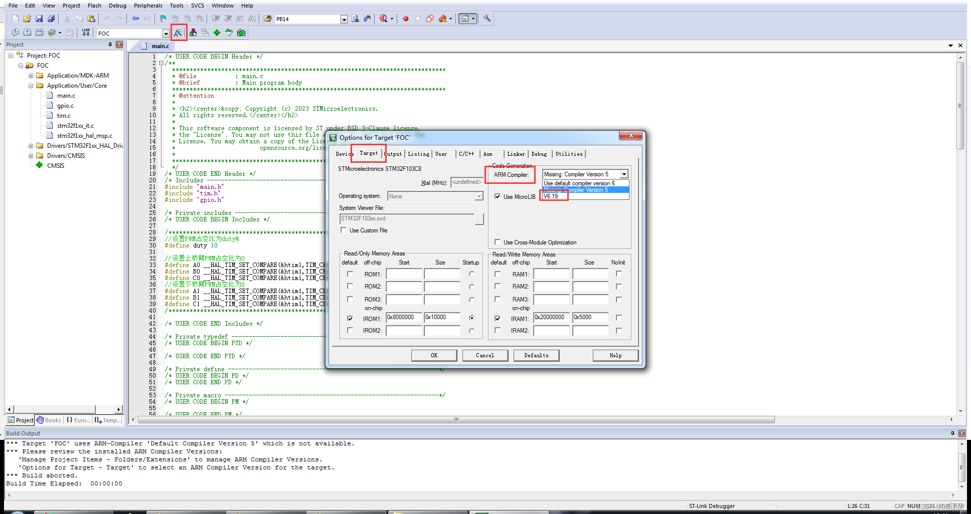
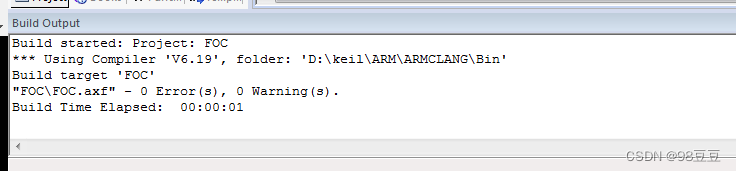
编译通过,0 error,0 warning。
在main.c函数中增添代码,main.c代码如下:
/* user code begin header */
/**
******************************************************************************
* @file : main.c
* @brief : main program body
******************************************************************************
* @attention
*
* <h2><center>© copyright (c) 2023 stmicroelectronics.
* all rights reserved.</center></h2>
*
* this software component is licensed by st under bsd 3-clause license,
* the "license"; you may not use this file except in compliance with the
* license. you may obtain a copy of the license at:
* opensource.org/licenses/bsd-3-clause
*
******************************************************************************
*/
/* user code end header */
/* includes ------------------------------------------------------------------*/
#include "main.h"
#include "tim.h"
#include "gpio.h"
/* private includes ----------------------------------------------------------*/
/* user code begin includes */
/***********************************************************************************************/
//按照cubemx中设置:apb2为72mhz,prescaler预分频系数为36-1,counter period(autoreload register)为100-1
//可计算pwm(定时器)周期为72mhz/((36-1)+1)/((100-1)+1)=20khz,也就是pwm(定时器)周期为0.00005s=50us

//设置pwm占空比为duty%
#define duty 10			//高电平在一个pwm中占空比为10%,换算为时间是0.000005s=5us的高电平时间
//设置(上桥臂)pwm占空比为0
#define a0 __hal_tim_set_compare(&htim1,tim_channel_1,0)
#define b0 __hal_tim_set_compare(&htim1,tim_channel_2,0)
#define c0 __hal_tim_set_compare(&htim1,tim_channel_3,0)
//设置(下桥臂)pwm占空比为10
#define a1 __hal_tim_set_compare(&htim1,tim_channel_1,duty)
#define b1 __hal_tim_set_compare(&htim1,tim_channel_2,duty)
#define c1 __hal_tim_set_compare(&htim1,tim_channel_3,duty)
/***********************************************************************************************/
/* user code end includes */
/* private typedef -----------------------------------------------------------*/
/* user code begin ptd */
/* user code end ptd */
/* private define ------------------------------------------------------------*/
/* user code begin pd */
/* user code end pd */
/* private macro -------------------------------------------------------------*/
/* user code begin pm */
/* user code end pm */
/* private variables ---------------------------------------------------------*/
/* user code begin pv */
/* user code end pv */
/* private function prototypes -----------------------------------------------*/
void systemclock_config(void);
/* user code begin pfp */
/* user code end pfp */
/* private user code ---------------------------------------------------------*/
/* user code begin 0 */
/* user code end 0 */
/**
* @brief the application entry point.
* @retval int
*/
int main(void)
{
/* user code begin 1 */
/* user code end 1 */
/* mcu configuration--------------------------------------------------------*/
/* reset of all peripherals, initializes the flash interface and the systick. */
hal_init();
/* user code begin init */
/* user code end init */
/* configure the system clock */
systemclock_config();
/* user code begin sysinit */
/* user code end sysinit */
/* initialize all configured peripherals */
mx_gpio_init();
mx_tim1_init();
/* user code begin 2 */
/***********************************************************************************************/
//开启pwm输出,输出6路pwm信号
hal_tim_pwm_start(&htim1,tim_channel_1);
hal_tim_pwm_start(&htim1,tim_channel_2);
hal_tim_pwm_start(&htim1,tim_channel_3);
hal_timex_pwmn_start(&htim1,tim_channel_1);
hal_timex_pwmn_start(&htim1,tim_channel_2);
hal_timex_pwmn_start(&htim1,tim_channel_3);
/***********************************************************************************************/
/* user code end 2 */
/* infinite loop */
/* user code begin while */
while (1)
{
/***********************************************************************************************/
		a1;b0;c0;			//打开a上、b下、c下		关闭a下、b上、c上
		hal_delay(10);
		a0;b1;c0;			//打开a下、b上、c下		关闭a上、b下、c上
		hal_delay(10);
		a0;b0;c1;			//打开a下、b下、c上		关闭a上、b上、c下
		hal_delay(10);
/***********************************************************************************************/
/* user code end while */
/* user code begin 3 */
}
/* user code end 3 */
}
/**
* @brief system clock configuration
* @retval none
*/
void systemclock_config(void)
{
rcc_oscinittypedef rcc_oscinitstruct = {0};
rcc_clkinittypedef rcc_clkinitstruct = {0};
/** initializes the rcc oscillators according to the specified parameters
* in the rcc_oscinittypedef structure.
*/
rcc_oscinitstruct.oscillatortype = rcc_oscillatortype_hse;
rcc_oscinitstruct.hsestate = rcc_hse_on;
rcc_oscinitstruct.hsepredivvalue = rcc_hse_prediv_div1;
rcc_oscinitstruct.hsistate = rcc_hsi_on;
rcc_oscinitstruct.pll.pllstate = rcc_pll_on;
rcc_oscinitstruct.pll.pllsource = rcc_pllsource_hse;
rcc_oscinitstruct.pll.pllmul = rcc_pll_mul9;
if (hal_rcc_oscconfig(&rcc_oscinitstruct) != hal_ok)
{
error_handler();
}
/** initializes the cpu, ahb and apb buses clocks
*/
rcc_clkinitstruct.clocktype = rcc_clocktype_hclk|rcc_clocktype_sysclk
|rcc_clocktype_pclk1|rcc_clocktype_pclk2;
rcc_clkinitstruct.sysclksource = rcc_sysclksource_pllclk;
rcc_clkinitstruct.ahbclkdivider = rcc_sysclk_div1;
rcc_clkinitstruct.apb1clkdivider = rcc_hclk_div2;
rcc_clkinitstruct.apb2clkdivider = rcc_hclk_div1;
if (hal_rcc_clockconfig(&rcc_clkinitstruct, flash_latency_2) != hal_ok)
{
error_handler();
}
}
/* user code begin 4 */
/* user code end 4 */
/**
* @brief this function is executed in case of error occurrence.
* @retval none
*/
void error_handler(void)
{
/* user code begin error_handler_debug */
/* user can add his own implementation to report the hal error return state */
__disable_irq();
while (1)
{
}
/* user code end error_handler_debug */
}
#ifdef use_full_assert
/**
* @brief reports the name of the source file and the source line number
* where the assert_param error has occurred.
* @param file: pointer to the source file name
* @param line: assert_param error line source number
* @retval none
*/
void assert_failed(uint8_t *file, uint32_t line)
{
/* user code begin 6 */
/* user can add his own implementation to report the file name and line number,
ex: printf("wrong parameters value: file %s on line %d\r\n", file, line) */
/* user code end 6 */
}
#endif /* use_full_assert */
/************************ (c) copyright stmicroelectronics *****end of file****/
3、结果分析
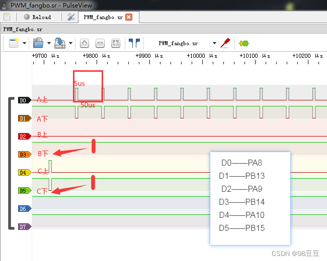
手上没有示波器,只有一个之前做的逻辑分析仪,接上stm32f103c8t6对应的6个引脚,对其进行逻辑分析,可以看出个大概。
我这里用到的是pa8、pa9、pa10、pab13、pb14、pb15:
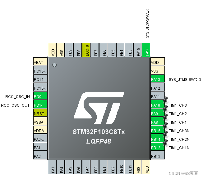

分析仪与stm32f103c8t6引脚对应关系如下:
按照
//按照cubemx中设置:apb2为72mhz,prescaler预分频系数为36-1,counter period(autoreload register)为100-1
//可计算pwm(定时器)周期为72mhz/((36-1)+1)/((100-1)+1)=20khz,也就是pwm(定时器)周期为0.00005s=50us
//设置pwm占空比为duty%
#define duty 10 //高电平在一个pwm中占空比为10%,换算为时间是0.000005s=5us的高电平时间
以及while中的
/***********************************************************************************************/
a1;b0;c0; //打开a上、b下、c下 关闭a下、b上、c上
hal_delay(10);
a0;b1;c0; //打开a下、b上、c下 关闭a上、b下、c上
hal_delay(10);
a0;b0;c1; //打开a下、b下、c上 关闭a上、b上、c下
hal_delay(10);
/***********************************************************************************************/
中的设置,理论上一个pwm的周期为50us,pwm中高电平信号时间为50us*10%=5us。
查看逻辑分析仪中的时间:
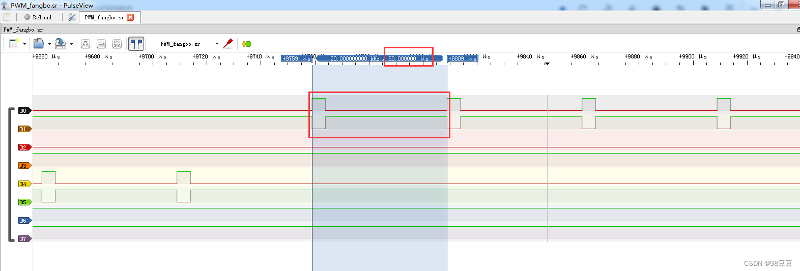
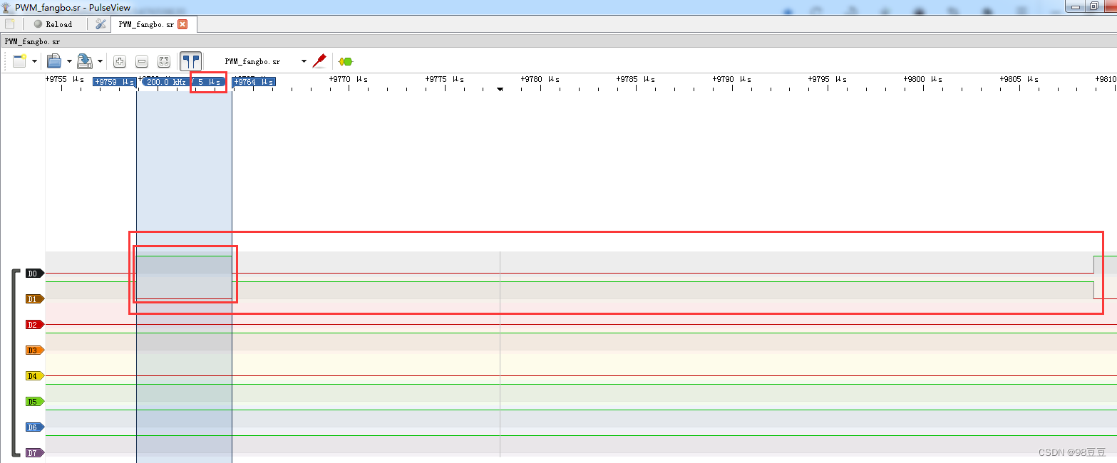
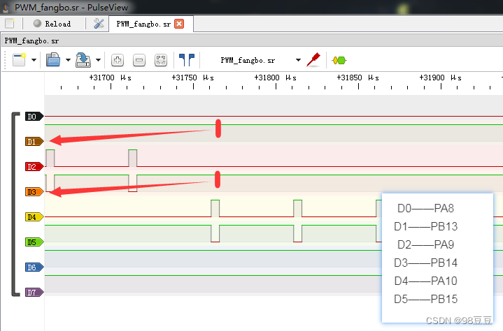
对照着逻辑分析仪查看不同端口的输出电平状态:
初始时刻
| / | a | b | c |
|---|---|---|---|
| 上桥臂 | 1(pa8) | 0(pa9) | 0(pa10) |
| 下桥臂 | 0(pb13) | 1(pb14) | 1(pb15) |
延迟10ms
| / | a | b | c |
|---|---|---|---|
| 上桥臂 | 0(pa8) | 1(pa9) | 0(pa10) |
| 下桥臂 | 1(pb13) | 0 (pb14) | 1(pb15) |

延迟10ms
| / | a | b | c |
|---|---|---|---|
| 上桥臂 | 0(pa8) | 0(pa9) | 1(pa10) |
| 下桥臂 | 1(pb13) | 1(pb14) | 0(pb15) |
参考的资料
1.有刷电机与无刷电机的区别,就是这么简单明了
2.一文看懂有刷电机与无刷电机的工作原理及区别
3.【自制foc驱动器】深入浅出讲解foc算法与svpwm技术


发表评论