本文使用ps-spi实现flash读写,ps-spi的基础资料参考xilinx ug1085的文档说明,其基础使用方法是,配置spi模式,控制txfifo/rxfifo,zynq的ip自动完成发送txfifo数据,接收数据到rxfifo,fifo深度为128byte。本文介绍了使用ps-spi的flash开发。
软硬件介绍:
- 硬件平台:xilinx zynq
- flash芯片:华邦w25q80
- 软件平台:vitis standalone
芯片信息/配置:
- 容量:8mbit
- spi时钟:25mhz
- io电平:3.3v
- spi fifo深度:128byte
- spi 标准模式
方案:
在zynq平台上使用ps的spi进行读写flash芯片,约束emio芯片管脚,在vitis上读写spi总线。
测试项目:
- 擦除、读、写功能
- 芯片容量
- 擦除、读、写速度
硬件设计
- 使能ps端的spi(spi0)模块,fifo位宽8bit
- 约束cs/di/do/clk管脚
- 生成xsa,提供给软件
软件设计
- 使用ps spi功能读写寄存器
- 封装读id、写使能、读取状态、擦除、读、写接口(c语言)。
调试和测试流程
- 读取芯片id,验证spi通路
- 验证全片擦除、页写入、读功能
- 页写入、读功能, 验证数据读写正确性
- 容量测试
- 测试读写时间
调试手段
- 发送数据:写ps-spi对应的写缓存地址,写入数据到“写fifo缓冲区”,等待发送完成
- 读取数据:读ps-spi对应的读缓存地址,读取“读fifo缓冲区”数据,等待读取完成
- 信号分析:测试过程中使用逻辑分析仪抓取cs/di/do/clk信号。
#define spips_recv_byte(baseaddress) \
		xil_in8((baseaddress) + xspips_rxd_offset)

#define spips_send_byte(baseaddress, data) \
		xil_out8((baseaddress) + xspips_txd_offset, (data))

void spi_read(int byte_count)
{
        int count;
        u32 status_reg;

        status_reg = xspips_readreg(g_spi0_handle.config.baseaddress,
                                        xspips_sr_offset);

        /*
         * polling the rx buffer for data
         */
        do{
                status_reg = xspips_readreg(g_spi0_handle.config.baseaddress,
                                        xspips_sr_offset);
        }while(!(status_reg & xspips_ixr_rxnempty_mask));


        /*
         * reading the rx buffer
         */

        for(count = 0; count < byte_count; count++){
                g_read_buffer[count] = spips_recv_byte(
                                g_spi0_handle.config.baseaddress);
        }

}

void spi_write(u8 *send_buffer, int byte_count)
{
        u32 status_reg;
        int trans_count = 0;

        status_reg = xspips_readreg(g_spi0_handle.config.baseaddress,
                                xspips_sr_offset);

        while ((byte_count > 0) &&
                (trans_count < xspips_fifo_depth)) {
                spips_send_byte(g_spi0_handle.config.baseaddress,
                                *send_buffer);
                send_buffer++;
                ++trans_count;
                byte_count--;
        }

        /*
         * wait for the transfer to finish by polling tx fifo status.
         */
        do {
                status_reg = xspips_readreg(
                                g_spi0_handle.config.baseaddress,
                                        xspips_sr_offset);
        } while ((status_reg & xspips_ixr_txow_mask) == 0);

}
代码:spi读写接口
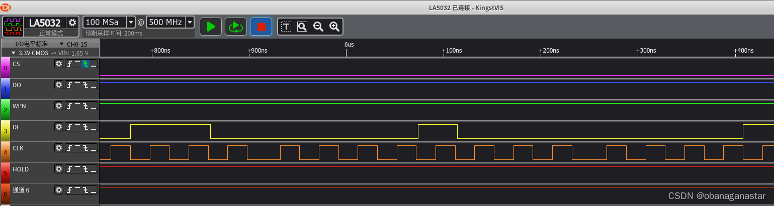
图:逻辑分析仪
1.读取芯片id,验证spi通路
- 写入"唤醒寄存器0xab",后面再发送3个字节(数据0),共发送4个字节;再发送一个字节(为了提供时钟),读取fifo数据5字节。
char release_powerdown_and_read_id()
{
	memset(g_write_buffer, 0x00, sizeof(g_write_buffer));
    g_write_buffer[0] = 0xab;
    //cs = 1
    set_csn();
    usleep(10);
    //cs = 0
    set_cs0();
    spi_write(g_write_buffer,5);
    set_csn();
    spi_read(5);
    return g_read_buffer[4];
}
代码:读id
注意的是,spi只要有时钟,“读fifo缓冲区”就会写入数据(miso)。主机发送5个字节,接着读取5个字节,丢弃前4个数据,第5个就是读到的id。 0xff 0xff 0xff 0xff 0x13
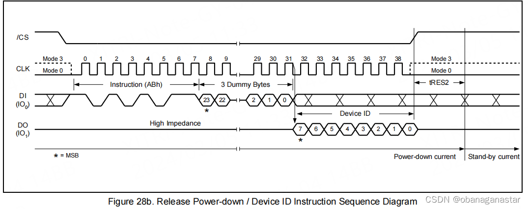
小结:读到的id是0x13,和datasheet一致。
2.验证全片擦除
执行操作前,先配置写使能能为1,读取状态寄存器
全片擦除,写入"擦除全片寄存器0xc7"
等待busy信号为0时结束,判断信号间隔为1ms(参考官方驱动)
注意的是写完后,写时能标记为会置0
int wait_busy(int max_count)
{
	int r,busy,busy_cnt = 0x00;
	r = 0;
	do {
		busy = is_busy();
		if(busy == 1)
			usleep(1000);
		busy_cnt += 1;
		if (max_count > 0)
		{
			if (busy == 0)
			{
				r = 0;
				break;
			}
			if (busy_cnt > max_count)
			{
				r = -1;
				break;
			}
		}
	} while(busy == 1);
	return r;
}

void erase_entire()
{
    set_write_enable();
	g_write_buffer[0] = 0xc7;
	set_csn();
	usleep(10);
	set_cs0();
	spi_write(g_write_buffer,1);
	set_csn();
	spi_read(1);
	wait_busy(1000);
	return ;
}
代码:擦除全片
----------------------------------------
...erase entire chip...
<erase> entire consume time:831 ms
----------------------------------------
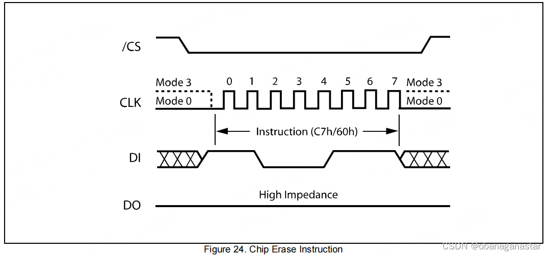
小结:全片擦除用了0.8s,比手册提供的2s典型值小。
3.页写入、读功能, 验证数据读写正确性
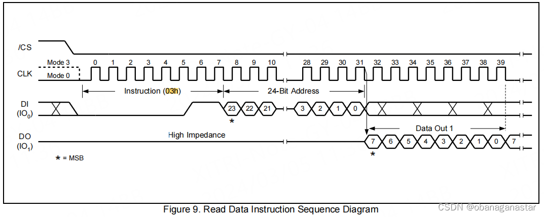
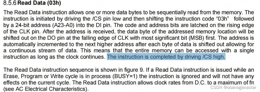
页读取
写入"读页数据寄存器0x03",后面跟一个24位地址,按照手册要求先发送高位地址,即依次发送addr[23:16],addr[15:8],addr[7:0]。主机还要继续写入提供时钟,写入一个页的数据(0)。读取“读fifo缓冲区”数据,读取一个页的数据量,得到读取内容。
void page_read(int address, unsigned char * recv, int size)
{
	int i;
	set_csn();
	usleep(10);
	set_cs0();
	g_write_buffer[0] = 0x03;
	g_write_buffer[1] = address >> 16;
	g_write_buffer[2] = address >> 8;
	g_write_buffer[3] = address >> 0;
	spi_write(g_write_buffer,4);
	spi_read(4);
	g_write_buffer[0] = 0;

	memset(g_write_buffer, 0x00, sizeof(g_write_buffer));
	if (size > 128)
	{
		spi_write(g_write_buffer,128);
		spi_read(128);
		memcpy(recv, g_read_buffer, 128);
		spi_write(g_write_buffer + 128,size - 128);
		spi_read(size - 128);
		memcpy(recv + 128, g_read_buffer, size - 128);
	}
	else
	{
		spi_write(g_write_buffer, size);
		spi_read(size);
		memcpy(recv, g_read_buffer, size);
	}

	set_csn();
	return;
}
代码:页读取
页写入
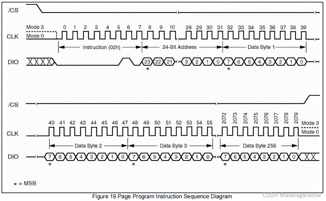
写入"写页数据寄存器0x02",后面跟一个24位地址,按照手册要求先发送高位地址,即依次发送addr[23:16],addr[15:8],addr[7:0]。主机继续写入一个页的数据,页数据pattern是一个递增数据。
//pattern
u8 data[] = {0x00,0x01,0x02....0x0ff};
读取“读fifo缓冲区”数据,排空无用“读缓冲数据”。
void page_write(int address, unsigned char * data, int size)
{
	//int i;
	set_write_enable();
	set_csn();
	usleep(10);
	set_cs0();
	g_write_buffer[0] = 0x02;
	g_write_buffer[1] = address >> 16;
	g_write_buffer[2] = address >> 8;
	g_write_buffer[3] = address >> 0;
	spi_write(g_write_buffer,4);
	spi_read(4);

	if (size > 128)
	{
		spi_write(data,128);
		spi_read(128);

		spi_write(data + 128,size - 128);
		spi_read(size - 128);
	}
	else
	{
		spi_write(data,size);
		spi_read(size);
	}

	wait_busy(1000);
	set_csn();
	return;
}
代码:页写入
验证
- 执行“擦除”操作
- 执行“页写入”操作
- 执行“页读取”操作
- 打印读取数据,比较写入数据和读取数据内容,使用memcmp进行比较。
void page_rw_test()
{
    char send_data[page_size] = {...};//自行填充
    char recv_data[page_size];
    erase_entire();
    page_write(0x00, send_data, page_size);
    page_read(0x00,  recv_data, page_size);
    r = memcmp(send_data, recv_data, page_size);
    return r;
}
代码:页读写验证
小结:读写功能正常,数据比较一致。
4.容量测试
方法:每4个字节当作一个单元,每个单元数据递增1。写入再读出作比较。
芯片共有16x16x16个4k个页,往4k个页写入递增数据(0,262143)。打印部分页内容,对比所有写入数据和读取数据,使用memcmp进行比较。
表:地址和容量地址
| byte_address | 0 | 1 | 2 | 3 | 4 | 5 | 6 | 7 | .. | .. | .. | .. | 8388604 | 8388605 | 8388606 | 8388607 | |
| vol_address | 0 | 1 | ........ | 262143 | |||||||||||||
| data | 0 | 1 | ........ | 262143 | |||||||||||||
小结:打印内容符合递增预期,数据比较一致。
5.测试读写时间
容量测试加入时间打印,分别记录擦除时间、写入时间和读取时间。
时间计数方式,采用读取cpu计数器计数,转换成时间。
write_data/read_data是page_write/page_read的封装,可以写入/读取任意数据。
int entire_volume_test(const int value_start, int step)
{
	int blkn, r, value, i,last_value;
	int escape;
	xtime start,end;
	blkn = block_number;
	printf("[ entire volume test ]\r\n");
	printf("[information]:\r\n");
	printf("----------------------------------------\r\n");
	printf("      capicity( bit ):%d\r\n", blkn * block_size * 8);
	printf("      capicity(1byte):%d\r\n", blkn * block_size);
	printf("      capicity(4byte):%d   [*]\r\n", blkn * block_size/4);
	printf("      spi clk        :%d mhz\r\n", 25);
	printf("----------------------------------------\r\n");
	printf("[test parttern] value start:%d,step:%d\n", value_start, step);
	printf("[test parttern] value range:(%d , %d)\n", value_start, step * (blkn * block_size/4 - 1));
	printf("----------------------------------------\r\n");
	printf("...erase entire chip...\r\n");
	start = get_sys_count();
	erase_entire();
	end = get_sys_count();
	escape =  get_useconds(start, end);
	printf("<erase> entire consume time:%02d ms \r\n", escape/1000);
	usleep(200000);
	last_value = step * (blkn * block_size/4 - 1);

	printf("    fill data\r\n");
	value = value_start;
	for (i = 0; i < blkn * block_size/4; i++)
	{
		g_data[i * 4 + 3 ] = (value >> 24) & 0xff;
		g_data[i * 4 + 2 ] = (value >> 16) & 0xff;
		g_data[i * 4 + 1 ] = (value >>  8) & 0xff;
		g_data[i * 4 + 0 ] = (value >>  0) & 0xff;
		value += step;
	}
	printf("    write data sequence\r\n");
	start = get_sys_count();
	write_data(0, g_data,        blkn * block_size);
	end = get_sys_count();
	escape =  get_useconds(start, end);
	printf("<write> data consume time:%02d ms \r\n", escape/1000);

	printf("    reading.....\r\n");
	start = get_sys_count();
	read_data (0, g_recv_buffer,blkn * block_size);
	end = get_sys_count();
	escape =  get_useconds(start, end);
	printf("<read> consume time:%02d ms \r\n", escape/1000);

	printf("    dump last 2 page \r\n");
	printf("value will range:(%08d , %08d)\r\n", 1 + last_value - 2 * page_size/ 4, last_value - 1 * page_size/ 4);
	dec_print(g_recv_buffer + (blkn * block_size - 2 * page_size) , page_size/4);

	printf("value will range:(%08d , %08d)\r\n", 1 + last_value - 1 * page_size/ 4, last_value - 0 * page_size/ 4);
	dec_print(g_recv_buffer + (blkn * block_size - 1 * page_size) , page_size/4);

	printf("compare <write data> and <read data> values, compare size:%d bytes\n", blkn * block_size);
	printf("----------------------------------------\r\n");
	if (memcmp(g_data, g_recv_buffer, blkn * block_size) == 0)
	{
		printf("  [*] <pass> volume test !!!\r\n");
		printf("----------------------------------------\r\n");
		return 0;
	}
	printf("[*] !!<fail> volume test !!!\r\n");
	printf("----------------------------------------\r\n");
	return -1;
}
代码:容量测试
<write> page data consume time:1346 us
<read> page data consume time:275 us
...erase entire chip...
<erase> entire consume time:831 ms
fill data
write data sequence
<write> data consume time:5509 ms
reading.....
<read> consume time:1127 ms
----------------------------------------
[*] <pass> volume test !!!
----------------------------------------
记录测试结果到下表
| 测试项目 | 测试值(ms) | 参考值[典型值,最大值](ms) |
| 页写入时间 | 1.34 | [0.8, 3] |
| 页读取时间 | 0.28 | / |
| 全片擦除时间 | 831 | [2000, 6000] |
| 全片写入时间 | 5509 | [3276,24576] |
| 全片读取时间 | 1127 | / |
表:测试结果
总结:擦除速度比datasheet参考值快,其他均正常。
其他相关
flash读写特性
flash的特性是,写数据只能将1写为0,0不能写为1。擦除数据是将所有数据都写为1。因此如果想在已经数据的flash上写入新的数据,则必须先擦除。
芯片地址相关
以wq25q80为例,一个地址24位,由块地址、扇地址、页地址、页内偏移组成。
#define address(block, sector, page, offset) ((block) << 16 | (sector) << 12 | (page) << 8 | (offset))代码:使用c语言表示芯片地址
| 地址项 | 块地址 | 扇区地址 | 页地址 | 页内偏移 |
| 地址大小(bit) | 4(冗余)+4 | 4 | 4 | 8 |
表:wq25q80地址
比如一个地址0x04e3aa,表示块地址0x04,扇区地址0xe,页地址0x03,页内偏移0xaa。
关于cs使用
使用芯片时候需要把cs引脚拉低,在命令写完成后需要把cs引脚拉高。手册里都会有"the instruction is completed by driving /cs high"的说明,这也成为flash芯片操作的通用操作。
关于ps-spi软件配置
可以配置cs控制模式、时钟频率,时钟频率通过spi主频分频得到,分频系数可配置。
int spi_init() {
        unsigned int config_value;
        int status;
        char spi_dev_id = spi_device_id;
        xspips_config *spi_config;


        /*
         * initialize the spi device.
         */

        spi_config = xspips_lookupconfig(spi_dev_id);
        if (null == spi_config) {
                return xst_failure;
        }


        status = xspips_cfginitialize(&g_spi_handle, spi_config, spi_config->baseaddress);
        if (status != xst_success) {
                return xst_failure;
        }


        /*
         * perform a self-test to check hardware build.
         */

        status = xspips_selftest(&g_spi_handle);
        if (status != xst_success) {
                return xst_failure;
        }

        xspips_resethw(spi_config->baseaddress);

        printf("%s self test succ\r\n", __func__);

        status = xspips_setoptions(&g_spi_handle, xspips_master_option | xspips_force_sselect_option);
        //status = xspips_setoptions(&g_spi_handle, xspips_master_option);
        if (status != xst_success) {
                printf("%s xspips_setoptions fail\n", __func__);
                return xst_failure;

        }
        /*
         * ps spi clk domain 200mhz
         * */
        status = xspips_setclkprescaler(&g_spi_handle, xspips_clk_prescale_8);
        if (status != xst_success) {
                printf("%s xspips_setclkprescaler fail\n", __func__);
                return xst_failure;
        }

        xspips_enable(&g_spi_handle);
        printf("spi <%d> config finish\r\n", spi_dev_id);

        //config_value =
        xspips_readreg(g_spi_handle.config.baseaddress,xspips_cr_offset);
        //printf("config_value :0x%08x\n", config_value);

        return xst_success;

}
关于发送间隔设置
我在测试多路spi的时候,发现同型号芯片读写时间差别大,测试时钟sclk,表现上间隔不一致。查阅寄存器表后发现,“发送间隔”配置不一致。
“发送间隔”修改成一致后,测试读写时间一致。
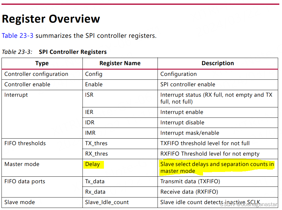
图:spi控制器寄存器列表

发表评论